Posterior Cervical Fusion: An Intraoperative Masterclass in Stabilization
Key Takeaway
Join us in the OR for a comprehensive masterclass on posterior cervical fusion. We'll meticulously detail patient positioning, surgical anatomy, and step-by-step execution of lateral mass screw fixation, pedicle screw placement, and various wiring techniques. Learn critical pearls, pitfalls, and postoperative management to achieve robust spinal stabilization and optimal patient outcomes. This immersive guide is essential for orthopaedic fellows.
Comprehensive Introduction and Patho-Epidemiology
Posterior cervical fusion (PCF) with instrumentation represents a foundational pillar in the armamentarium of the modern spine surgeon. Historically evolving from simple onlay bone grafting and cerclage wiring techniques—pioneered by Rogers and Bohlman—to highly sophisticated, rigid screw-rod constructs, the primary objective remains unchanged: to achieve robust, immediate biomechanical stabilization that facilitates solid, long-term arthrodesis. This procedure is frequently indicated following extensive posterior decompression (such as multilevel laminectomy) to prevent post-laminectomy kyphosis, or as a primary intervention for managing gross segmental instability. Executing a successful PCF is not merely an exercise in carpentry; it demands a profound, three-dimensional understanding of complex cervical anatomy, a deep respect for adjacent neurovascular structures, and the meticulous application of biomechanical principles.
The pathophysiology of cervical instability necessitating posterior fusion is incredibly diverse, encompassing traumatic, degenerative, neoplastic, and infectious etiologies. Traumatic injuries, such as bilateral facet dislocations or unstable burst fractures, often catastrophically disrupt the posterior tension band, requiring rigid posterior fixation to restore anatomic alignment and prevent devastating neurologic decline. In the degenerative spine, multilevel cervical spondylotic myelopathy (CSM) or ossification of the posterior longitudinal ligament (OPLL) frequently necessitates wide posterior decompression. Resection of the posterior elements inherently destabilizes the cervical column, predisposing the patient to progressive kyphotic deformity if not accompanied by a concomitant instrumented fusion. The biomechanical failure of the posterior column shifts the instantaneous axis of rotation anteriorly, increasing compressive forces on the anterior vertebral bodies and accelerating adjacent segment degeneration.
Epidemiologically, as the global population ages, the incidence of degenerative cervical pathology requiring surgical intervention is rising exponentially. The shift toward rigid internal fixation—specifically utilizing lateral mass and pedicle screws—has dramatically improved fusion rates and clinical outcomes compared to historical non-instrumented or wire-based cohorts. These modern constructs provide superior resistance to flexion, extension, axial rotation, and lateral bending forces, allowing for early patient mobilization and drastically reducing the reliance on cumbersome external orthoses like halo vests. The evolution of polyaxial screw heads and pre-contoured titanium or cobalt-chrome rods has further refined the surgeon's ability to restore cervical lordosis, a critical factor in optimizing long-term health-related quality of life (HRQoL) metrics.
However, the mastery of posterior cervical stabilization requires an appreciation of the delicate balance between rigid fixation and the inherent risks of inserting metal into a highly constrained anatomic corridor. The margin for error is measured in millimeters. Misplaced instrumentation can result in devastating complications, including vertebral artery laceration, spinal cord injury, or exiting nerve root impingement. Thus, a comprehensive understanding of the patho-epidemiology must be coupled with rigorous preoperative planning and flawless intraoperative execution. The modern spine surgeon must navigate these treacherous waters with a combination of tactile feedback, anatomical knowledge, and advanced intraoperative imaging.
Detailed Surgical Anatomy and Biomechanics
Osteology and Morphometry of the Subaxial Cervical Spine
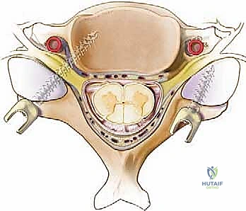
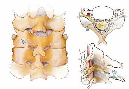
A profound mastery of posterior cervical surgical anatomy is the absolute prerequisite for safe and effective instrumentation. The osteology of the subaxial cervical spine (C3-C7) presents unique challenges due to its diminutive size and complex geometry. The spinous processes vary significantly; C2 is characteristically large and bifid, providing a robust anchor for muscle attachments, while C7 (the vertebra prominens) is typically the longest and non-bifid, serving as a critical landmark for clinical and surgical orientation. The laminae form the bony roof of the spinal canal, connecting the spinous processes to the lateral masses. The lateral masses themselves are quadrangular columns of cancellous bone bounded by cortical shells, formed by the confluence of the superior and inferior articular processes. These structures serve as the primary target for subaxial cervical screw fixation, requiring precise identification of their geographic center for optimal screw purchase.
The pedicles of the subaxial cervical spine are short, thick bony cylinders connecting the lateral masses to the vertebral bodies. Their small dimensions and intimate relationship with critical neurovascular structures make them highly challenging targets. A thorough understanding of pedicle morphometry is critical. The pedicle outer width dictates the feasibility of screw placement; generally, a width of less than 4 mm precludes safe instrumentation. The largest pedicles are typically found at C2 (averaging 6.9 mm) and C7 (averaging 6.7 mm), while the mid-cervical pedicles (C3-C5) are the narrowest (averaging 5.3 to 5.7 mm). Furthermore, the axial pedicle angle varies, being least angled at C2 (25-30 degrees medially) and most acutely angled at C3 (averaging 44 degrees), gradually decreasing toward C7.
Biomechanically, the subaxial cervical spine is designed for a wide range of motion, sacrificing inherent stability for mobility. The facet joints are oriented at approximately 45 degrees to the axial plane in the subaxial spine, allowing for coupled axial rotation and lateral bending. When instrumentation is applied, lateral mass screws rely primarily on the pullout strength of the relatively thin cortical bone of the posterior and anterior lateral mass walls. Conversely, cervical pedicle screws engage the dense cortical cylinder of the pedicle and the cancellous bone of the vertebral body, providing a construct that is biomechanically superior to lateral mass screws, particularly in resisting pullout forces in osteoporotic bone or severe deformity corrections.
Musculoligamentous Anatomy and Tension Band Mechanics
Navigating the muscular and ligamentous intervals requires meticulous dissection to preserve function and minimize postoperative morbidity. The superficial layer comprises the trapezius, rhomboids, and splenius capitis/cervicis. The deep paraspinal muscles, including the semispinalis cervicis/capitis, multifidus, and rotatores, must be dissected subperiosteally off the spinous processes and laminae. Preservation of the muscular attachments to the C2 spinous process is particularly critical; aggressive detachment of the semispinalis cervicis can lead to profound postoperative axial neck pain and progressive kyphotic deformity due to the loss of the dynamic posterior tension band.
The nuchal ligament (ligamentum nuchae) is a robust, avascular fibrous septum extending from the external occipital protuberance to the spinous process of C7. It serves as a major site for muscle attachment and acts as a passive restraint to hyperflexion. During the surgical approach, staying strictly within the midline avascular plane of the nuchal ligament is paramount to minimizing intraoperative blood loss and preserving the vascular supply to the paraspinal musculature. Straying from this plane results in immediate, unnecessary hemorrhage from the muscular arterial feeders.
The facet joint capsules are thick, fibrous structures that provide significant resistance to anterior translation and hyperflexion. During fusion bed preparation, it is imperative to meticulously excise the capsule at the levels to be fused to expose the articular cartilage for decortication. However, the surgeon must exercise extreme caution to preserve the facet capsules of the adjacent, unfused segments. Iatrogenic disruption of the adjacent segment facet capsule is a well-documented risk factor for accelerated adjacent segment disease (ASD) and subsequent junctional instability.
Neurovascular Topography and High-Risk Corridors
The neurovascular risks in posterior cervical surgery are substantial and ever-present. The spinal cord and dural sac lie immediately ventral to the laminae; any ventral cortical breach during drilling or screw placement risks catastrophic neurologic injury. The epidural venous plexus, particularly prominent in the lateral gutters, can be a source of copious bleeding if the epidural space is violated. The cervical nerve roots exit through the neural foramina, located lateral to the spinal canal and anterior to the facet joints. Crucially, the exiting nerve root typically lies superior and anterior to its corresponding pedicle, making it highly vulnerable to superiorly errant pedicle screws or excessively long lateral mass screws that breach the ventral cortex of the lateral mass.
The vertebral artery, ascending through the foramen transversarium from C6 to C2, represents the most feared vascular hazard. In the subaxial spine (C3-C6), the artery lies immediately lateral to the uncinate process and anterior to the nerve root, in perilous proximity to the lateral mass and pedicle. Trajectories for lateral mass screws must be meticulously planned to exit lateral and superior to this critical vessel. A medial or excessively anterior breach during lateral mass preparation can result in a devastating vertebral artery laceration, leading to massive hemorrhage, pseudoaneurysm formation, or posterior circulation stroke.
At the C2 level, the vertebral artery typically courses laterally after exiting the C3 foramen transversarium, then loops medially and superiorly to enter the C2 foramen. This medial loop, or "high-riding" vertebral artery, is present in up to 20% of patients and severely compromises the bony corridor available for C2 pars or pedicle screw placement. Failure to recognize this anomaly on preoperative imaging is a common cause of iatrogenic vertebral artery injury during C2 instrumentation.
Exhaustive Indications and Contraindications
The decision to proceed with a posterior cervical fusion must be predicated on a rigorous evaluation of the patient's pathology, biomechanical stability, and overall physiologic status. While posterior approaches offer excellent visualization and robust fixation, they are not universally applicable to all cervical pathologies.
| Category | Specific Conditions |
|---|---|
| Primary Indications | Multilevel cervical spondylotic myelopathy (CSM) requiring laminectomy; Ossification of the posterior longitudinal ligament (OPLL); Traumatic instability (e.g., bilateral facet dislocations, unstable burst fractures); Neoplastic destruction of posterior elements; Iatrogenic post-laminectomy kyphosis; Pseudarthrosis following anterior cervical discectomy and fusion (ACDF). |
| Absolute Contraindications | Active systemic or local infection (unless the procedure is specifically for debridement and stabilization of osteomyelitis/discitis); Severe medical comorbidities precluding general anesthesia or prone positioning; Irreversible, profound osteoporosis precluding any form of hardware purchase. |
| Relative Contraindications | Fixed, rigid cervical kyphosis (often requires an anterior release or combined anterior-posterior approach); Severe anterior column deficiency without anterior support; Poor soft tissue envelope precluding adequate wound closure. |
Deformity and Instability Paradigms
Indications for posterior cervical fusion are broadly categorized into instability, deformity, and the need for stabilization following decompression. In the setting of trauma, posterior fusion is the gold standard for tension band failures, such as flexion-distraction injuries. For degenerative conditions, when a multilevel laminectomy is performed to decompress the spinal cord, a concomitant instrumented fusion is strongly recommended to prevent the predictable complication of post-laminectomy kyphosis, particularly in patients with a straight or already kyphotic preoperative alignment.
Contraindications must be carefully weighed. A purely posterior approach is relatively contraindicated in the setting of a fixed, rigid kyphotic deformity. In such cases, the posterior elements are under tension, and attempting to pull the spine into lordosis from a posterior-only approach places extreme stress on the hardware, leading to a high risk of screw pullout or rod fracture. These patients often require an anterior release (e.g., multilevel ACDF or corpectomy) prior to posterior stabilization. The "chin-on-chest" deformity seen in severe ankylosing spondylitis or advanced degenerative kyphosis requires complex osteotomies (e.g., pedicle subtraction osteotomy) that go beyond standard posterior fusion techniques.
Furthermore, severe osteoporosis significantly degrades the pullout strength of lateral mass and pedicle screws, necessitating the use of longer constructs, larger diameter screws, or adjunctive fixation techniques to achieve adequate stability. In patients with profound anterior column deficiency—such as that caused by a destructive metastatic tumor or severe osteomyelitis—a posterior-only construct will eventually fail due to cyclical loading and lack of anterior load-sharing. These scenarios mandate a combined anterior-posterior approach to reconstruct the anterior weight-bearing column and provide a posterior tension band.
Pre-Operative Planning, Templating, and Patient Positioning
Advanced Imaging Modalities and Trajectory Templating
Before a scalpel touches the skin, exhaustive preoperative planning is the blueprint for surgical success. For any posterior cervical instrumentation, rigorous review of high-resolution preoperative imaging is absolutely non-negotiable. Plain radiographs provide a baseline assessment of global sagittal alignment, dynamic instability on flexion-extension views, and overall bone quality. However, advanced cross-sectional imaging is mandatory for safe hardware placement.
Computed Tomography (CT) scans serve as our primary roadmap for bony architecture. We systematically scrutinize the lateral masses for their quadrilateral shape, volume, and bone density. When pedicle screw fixation is contemplated, we meticulously analyze the pedicle outer width, height, and trajectory angle at each specific level from C2 to C7. As previously noted, a pedicle outer diameter of less than 4 mm generally precludes safe screw insertion. We utilize multiplanar reconstructions to measure the exact medial angulation required and to identify any bony anomalies, such as blunted or sclerotic pedicles, which may alter our surgical strategy. The use of 3D-reconstructed CT models can further enhance the surgeon's spatial understanding of complex deformities.
Magnetic Resonance Imaging (MRI) provides indispensable data regarding the neural elements, dural sac, and soft tissue envelope. For instrumentation planning, we specifically interrogate the axial and sagittal T2-weighted sequences to map the course of the vertebral artery within the foramen transversarium. We must identify any anomalous medial loops or tortuosities of the vertebral artery, particularly from C3 to C6, which could place the vessel at extreme risk during lateral mass or pedicle screw preparation. At C2, the vertebral artery is generally positioned lateral to the ideal pedicle screw trajectory, while at C7, the artery is frequently absent from the foramen transversarium entirely, enhancing the safety profile of C7 pedicle screws.
Patient Positioning and Cranial Fixation Optimization
Patient positioning is a critical, highly choreographed phase of the operation that directly impacts surgical access, alignment, and patient safety. The patient is carefully transferred to a radiolucent operating table in the prone position. Rigid cranial fixation using a Mayfield head clamp or similar skull-pinning device is mandatory. This ensures absolute control over cervical alignment and prevents catastrophic, inadvertent movement during drilling and instrumentation. The skull pins must be securely seated in the outer table of the calvarium, strictly avoiding the temporal squama, vascular sinuses, and major neurovascular bundles.
Once pinned, the patient's alignment is optimized. We aim for a neutral or slightly lordotic cervical posture, depending on the preoperative plan and the necessity to restore sagittal balance. Extreme care is taken to avoid hyperextension in myelopathic patients, as this can exacerbate cord compression via infolding of the ligamentum flavum. Longitudinal chest rolls are placed to elevate the thorax, allowing the abdomen to hang freely. This critical step minimizes intra-abdominal pressure, thereby reducing epidural venous engorgement and intraoperative bleeding.
The arms are carefully tucked at the patient's sides and heavily padded to prevent compressive neuropathies, particularly of the ulnar nerve at the cubital tunnel. Gentle caudal traction on the shoulders using broad tape can be applied to pull the shoulders out of the radiographic field, facilitating visualization of the lower cervical spine. Finally, the fluoroscopy C-arm is draped and positioned to ensure unimpeded access for both lateral and anteroposterior (AP) imaging. Intraoperative neuromonitoring (IONM), including somatosensory evoked potentials (SSEPs) and motor evoked potentials (MEPs), is established and baselines are obtained prior to positioning to detect any position-related neurologic compromise.
Step-by-Step Surgical Approach and Fixation Technique
Soft Tissue Dissection and Extensile Exposure
The execution of a posterior cervical fusion is an exercise in meticulous dissection, precise decompression, and rigid biomechanical stabilization. We begin with a precise midline skin incision, extending appropriately across the planned fusion levels. The subcutaneous dissection is carried down to the avascular nuchal ligament, which is incised strictly in the midline to minimize bleeding. Palpation of the bifid C2 spinous process and the prominent C7 spinous process helps confirm the level, though radiographic confirmation is always required.
Subperiosteal dissection is then performed using electrocautery and Cobb elevators. We start at the spinous processes and work laterally, hugging the bone to strip the paraspinal musculature off the laminae and lateral masses. The goal is to expose the entire quadrilateral surface of the lateral masses and the facet joints at all levels intended for fusion, while strictly preserving the facet capsules of the adjacent, unfused segments to prevent junctional instability. Meticulous hemostasis is maintained throughout this exposure phase using bipolar electrocautery and hemostatic agents.
Self-retaining retractors, such as Cerebellar or deep Gelpi retractors, are placed to maintain exposure. It is crucial to periodically release retractor tension throughout long cases to prevent ischemic necrosis of the paraspinal musculature. The lateral border of the lateral mass must be clearly defined to ensure accurate starting points for instrumentation.
Decompression and Fusion Bed Preparation
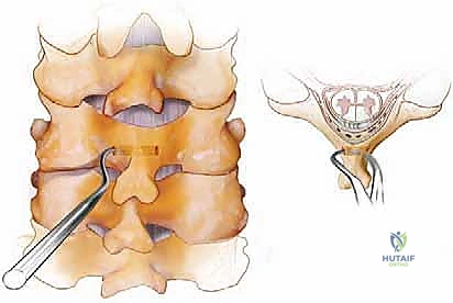
If neural decompression is indicated, such as a laminectomy for myelopathy, it is executed prior to final fusion bed preparation but often after the initial pilot holes for lateral mass screws are drilled, as the intact posterior elements provide a stable platform for drilling. Laminectomy is performed using a high-speed matchstick burr to create bilateral troughs at the lamina-lateral mass junction, followed by en bloc removal of the laminae using Kerrison rongeurs. Extreme care is taken to avoid downward pressure on the thecal sac.
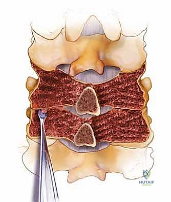
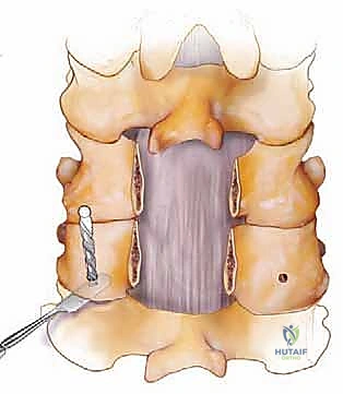
Once decompression is achieved, we turn our attention to the fusion bed. All remaining soft tissues, including interspinous ligaments and facet joint capsules at the fusion levels, are meticulously resected. Using a 3-mm high-speed burr, we decorticate the posterior cortical surfaces of the lateral masses, remaining laminae, and spinous processes to expose bleeding subcortical bone. The articular cartilage within the facet joints is aggressively debrided to create an optimal environment for osteogenesis.
Bone grafting is the biological foundation of the procedure. Autograft, typically harvested from the posterior iliac crest or derived from local laminectomy bone, remains the gold standard. The corticocancellous graft is morselized and meticulously onlaid over the decorticated posterior elements. Cancellous chips are directly packed into the decorticated facet joints to promote robust intra-articular arthrodesis. Demineralized bone matrix (DBM) or synthetic ceramics are frequently utilized as graft extenders.
Lateral Mass and Pedicle Screw Instrumentation
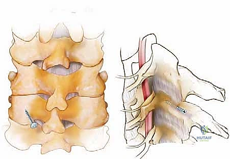
The Magerl and Roy-Camille techniques are the two primary methods for lateral mass screw insertion. The Magerl technique utilizes a starting point 1-2 mm medial and superior to the geographic center of the lateral mass. The trajectory is directed 25 degrees laterally and 25 degrees cranially (parallel to the facet joint). This lateral and cranial trajectory is specifically designed to avoid the vertebral artery and the exiting nerve root. A 2.5 mm drill is used, typically to a depth of 14 mm, followed by a blunt ball-tipped probe to palpate all five walls of the tract (four bony walls and a solid bottom, or a carefully breached ventral cortex). The tract is tapped, and a 3.5 mm polyaxial screw is inserted.
The Roy-Camille technique, conversely, utilizes a starting point at the exact center of the lateral mass, with a trajectory that is strictly orthogonal (perpendicular) to the posterior surface of the lateral mass, with 0 degrees of cranial angulation and 10 degrees of lateral angulation. While biomechanically sound, this trajectory carries a theoretically higher risk of nerve root injury if the ventral cortex is over-penetrated. Regardless of the technique, fluoroscopic or stereotactic navigation is heavily utilized to confirm trajectories.
Pedicle screw placement in the subaxial spine, particularly at C7, provides massive biomechanical pullout strength. The starting point for a C7 pedicle screw is typically at the intersection of the midpoint of the C7 lateral mass and the horizontal line bisecting the superior articular process. A high-speed burr is used to decorticate the starting point, and a small pedicle probe or drill is advanced with approximately 25-30 degrees of medial angulation, parallel to the superior endplate. The tract is meticulously probed to ensure no medial breach (which endangers the spinal cord) or lateral breach (which endangers the vertebral artery, if present at C7).
Interspinous Wiring and Adjunctive Techniques
While largely supplanted by screw-rod constructs, interspinous wiring remains a useful adjunct or primary fixation method in specific scenarios, particularly when lateral mass bone quality is poor or anatomy precludes screw placement. Wiring provides excellent resistance to flexion but is biomechanically inferior in resisting extension and rotational forces.
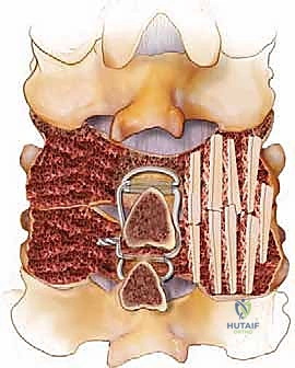
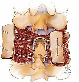
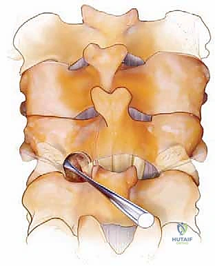
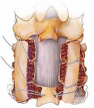
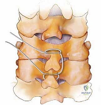
For simple interspinous wiring, a 2- to 3-mm drill bit is used to create holes at the base of the spinous process, near its junction with the lamina, to minimize the risk of wire pullout through the osteopenic tip. The Bohlman technique utilizes a braided titanium wire or cable passed through the base of the spinous processes of the cranial and caudal vertebrae, securing two corticocancellous strut grafts against the decorticated laminae. This creates a robust posterior tension band and provides an excellent bed for fusion.
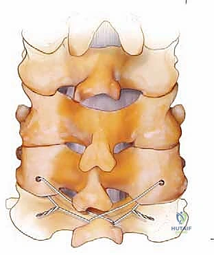
The Rogers technique involves passing a wire through drill holes in the adjacent spinous processes and creating a figure-of-eight loop to compress the segments. When combined with modern screw-rod constructs, wiring can be used to tether a cranial or caudal segment that is deemed too risky for screw placement, or to reinforce a construct in a patient with profound osteoporosis. However, the surgeon must be cautious, as passing wires through the epidural space carries an inherent risk of dural laceration or spinal cord contusion.
Complications, Incidence Rates, and Salvage Management
Despite meticulous technique, posterior cervical fusion carries a distinct profile of severe potential complications. The surgeon must be prepared to recognize and manage these intraoperative and postoperative challenges immediately.
| Complication | Estimated Incidence | Mechanism / Risk Factors | Salvage / Management Strategy |
|---|---|---|---|
| Vertebral Artery Injury | 0.5% - 2.0% | Lateral |
Clinical & Radiographic Imaging Archive