Ankle Distraction Arthroplasty: An Intraoperative Masterclass for Cartilage Regeneration
Key Takeaway
Welcome, fellows, to an immersive masterclass on ankle distraction arthroplasty. We'll meticulously cover patient selection, detailed surgical anatomy, and precise Ilizarov frame application. From initial incision to final distraction, learn every micro-step, critical pearls, and complication management for this cartilage regeneration technique. This procedure offers a vital alternative for younger patients seeking to defer fusion or replacement.
Comprehensive Introduction and Patho-Epidemiology
Ankle distraction arthroplasty represents a paradigm shift in the management of tibiotalar osteoarthritis, offering a sophisticated biological joint preservation strategy for younger, highly active patients. Historically, the treatment algorithm for end-stage ankle arthritis inevitably culminated in either ankle arthrodesis or total ankle arthroplasty. While arthrodesis provides reliable pain relief, it sacrifices joint kinematics and accelerates adjacent joint arthrosis. Conversely, total ankle arthroplasty, though preserving motion, is fraught with longevity concerns in patients under fifty years of age due to high mechanical demands and subsequent implant wear or aseptic loosening. Ankle distraction arthroplasty emerges as a compelling alternative, designed to defer or entirely circumvent these end-stage salvage procedures by facilitating intrinsic cartilage repair and modifying the intra-articular biochemical milieu.
The fundamental pathophysiology of ankle osteoarthritis differs markedly from that of the hip or knee. The vast majority of ankle arthritis is post-traumatic, typically manifesting secondary to malleolar fractures, recurrent ligamentous instability, or chronic microtrauma. This demographic is invariably younger, presenting a unique clinical challenge where functional expectations remain high, yet the articular cartilage has sustained irreversible mechanical and biochemical insults. The articular cartilage of the ankle is uniquely dense, possessing a higher proteoglycan concentration and lower water content than knee cartilage, rendering it exceptionally resilient to compressive loads but highly susceptible to shear forces following structural malalignment.
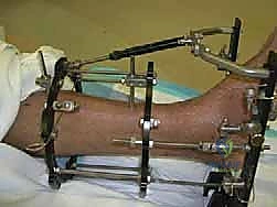
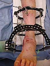
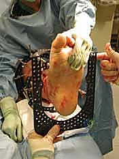
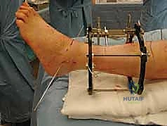
At its core, the biological rationale for ankle distraction arthroplasty relies on the principle of mechanical unloading coupled with intermittent hydrostatic pressure. By applying an Ilizarov or Taylor Spatial external fixator across the tibiotalar joint, the surgeon mechanically distracts the joint surfaces, typically achieving a 5-millimeter separation. This physical uncoupling immediately ceases the pathological mechanical grinding of eburnated bone surfaces. More importantly, when combined with controlled, intermittent weight-bearing, the distraction construct acts as a dynamic pump. This pumping action facilitates the ingress of synovial fluid, providing essential nutrients to the avascular chondrocytes, while simultaneously flushing out catabolic cytokines, matrix metalloproteinases (MMPs), and inflammatory mediators that perpetuate cartilage degradation.
Extensive in vitro and in vivo animal models have substantiated this hypothesis, demonstrating that mechanical offloading downregulates pro-inflammatory gene expression and upregulates the synthesis of type II collagen and aggrecan. Clinically, this manifests as a reduction in subchondral sclerosis, resolution of subchondral cysts, and a measurable increase in radiographic joint space over time. The success of this procedure is inextricably linked to meticulous patient selection, precise surgical execution, and rigorous postoperative rehabilitation, demanding a profound understanding of both biomechanics and cellular biology from the treating orthopedic surgeon.
Detailed Surgical Anatomy and Biomechanics
A profound, three-dimensional understanding of the lower extremity's surgical anatomy and biomechanics is the absolute prerequisite for successful ankle distraction arthroplasty. The orthopedic surgeon must conceptualize the ankle not merely as a simple hinge, but as a complex, multi-axial biomechanical unit encompassing the distal tibia, fibula, and the intricate articulations of the hindfoot. Normal ankle articular cartilage is an incredibly durable tissue, engineered to distribute loads that frequently exceed five times the patient's body weight during dynamic activities. Its highly organized ultrastructure, comprising specialized chondrocytes embedded within a complex extracellular matrix of type II collagen and hydrophilic proteoglycans, dictates its biomechanical resilience.
Osteology and coronal/sagittal alignment play a paramount role in the longevity of the native joint and the success of any joint preservation procedure. A well-aligned limb with a plantigrade foot is non-negotiable. The surgeon must meticulously assess the mechanical axis of the lower extremity, identifying any deformities arising from asymmetric articular wear, subchondral bony collapse, or intrinsic diaphyseal malalignment. The ideal biomechanical scenario for distraction is symmetric, uniform cartilage loss across the tibiotalar dome without significant extra-articular deviation. However, asymmetric wear patterns, such as varus or valgus intra-articular collapse, can be successfully managed provided that the surgeon simultaneously addresses the deforming forces through concurrent supramalleolar or calcaneal osteotomies.
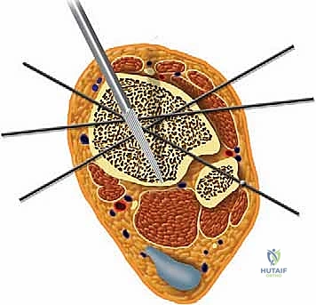
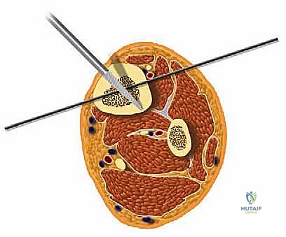
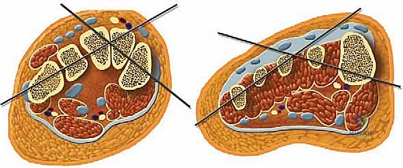
Navigating the neurovascular anatomy during the application of a multi-planar external fixator requires exacting precision to avoid catastrophic iatrogenic injury. The concept of "safe zones" for wire and half-pin insertion must be strictly adhered to. In the mid-to-distal tibia, the anterior compartment houses the critical deep peroneal nerve and anterior tibial artery, while the posterior compartment contains the tibial nerve and posterior tibial artery. Transfixion wires and half-pins are generally safest when directed through the anteromedial and posterolateral quadrants, strictly avoiding direct anterior-to-posterior or posterior-to-anterior trajectories. As the dissection approaches the ankle joint, these neurovascular structures become increasingly superficial.
At the level of the joint line, the saphenous nerve and vein course medially, the superficial peroneal nerve branches anterolaterally, and the sural nerve descends posterolaterally. The anterior tibial artery and deep peroneal nerve pass directly anterior to the tibiotalar joint capsule. Consequently, all pin and wire insertions in this vicinity mandate meticulous blunt dissection down to the periosteum using a hemostat, followed by the use of a tissue protector and rigorous fluoroscopic verification. Furthermore, ligamentous stability must be evaluated; lateral collateral ligament laxity or medial deltoid insufficiency must be surgically corrected prior to, or concomitantly with, the distraction to prevent asymmetric joint loading and subluxation within the frame.
Exhaustive Indications and Contraindications
The clinical efficacy of ankle distraction arthroplasty is highly dependent on stringent patient selection. The ideal candidate is a physiologically young, highly motivated, and compliant individual—typically under the age of 55—who presents with symptomatic, radiographically confirmed tibiotalar osteoarthritis. The pain must be primarily localized to the ankle joint and should correlate with weight-bearing activities. Crucially, the patient must possess a functional, albeit painful, preoperative arc of motion. A minimum of 20 to 30 degrees of total sagittal plane motion, including at least 5 to 10 degrees of dorsiflexion, is generally required. Joints that have progressed to near-ankylosis or severe fibrous contracture are unlikely to benefit from distraction, as the biological pumping mechanism relies on residual joint mobility.
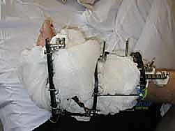
Psychosocial evaluation is equally critical. The patient must possess the cognitive capacity and psychological resilience to tolerate a bulky external fixator for a duration of 10 to 12 weeks. They must be committed to rigorous daily pin-site care, a strict postoperative rehabilitation protocol, and the inherent discomfort associated with transosseous wires. Patients with a history of non-compliance, active substance abuse, or severe, unmanaged psychiatric comorbidities are considered poor candidates. Furthermore, patients with heavy preoperative narcotic dependence often experience amplified pain responses to the fixator and generally exhibit poorer clinical outcomes.
Absolute contraindications include active intra-articular or peri-articular sepsis, severe peripheral vascular disease compromising the healing of pin tracts, and profound peripheral neuropathy (such as Charcot neuroarthropathy), which eliminates the protective pain feedback mechanisms necessary for safe frame wear. Relative contraindications include advanced chronological age (though physiological age is a more accurate determinant), inflammatory arthropathies (e.g., Rheumatoid Arthritis) where the systemic disease process outpaces localized cartilage repair, and severe, uncorrectable osteoporosis that precludes adequate transosseous wire and pin purchase.
| Category | Specific Conditions | Clinical Rationale |
|---|---|---|
| Primary Indications | Post-traumatic ankle osteoarthritis; Primary ankle osteoarthritis in younger patients (<55 years); Osteochondral lesions of the talus (diffuse). | Preserves joint anatomy; delays need for arthrodesis/arthroplasty; utilizes biological healing potential of unloaded cartilage. |
| Prerequisite Criteria | Minimum 20-30° total ROM; Minimum 5° dorsiflexion; Localized joint pain; High patient compliance. | Ensures dynamic fluid pumping mechanism can occur; guarantees patient can manage pin care and fixator burden. |
| Absolute Contraindications | Active joint infection/osteomyelitis; Severe peripheral vascular disease; Charcot neuroarthropathy; Ankylosed joint. | High risk of systemic spread, non-healing pin tracts, catastrophic frame failure, or inability to achieve distraction mechanics. |
| Relative Contraindications | Inflammatory arthropathy (e.g., RA); Severe osteoporosis; Heavy preoperative narcotic dependence; Unmanaged psychiatric illness. | Systemic disease may override local repair; poor bone stock leads to pin loosening; high failure rate due to pain intolerance or non-compliance. |
Pre-Operative Planning, Templating, and Patient Positioning
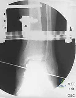
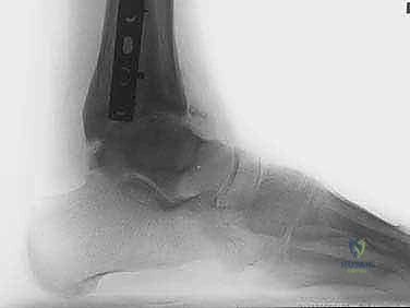
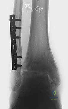
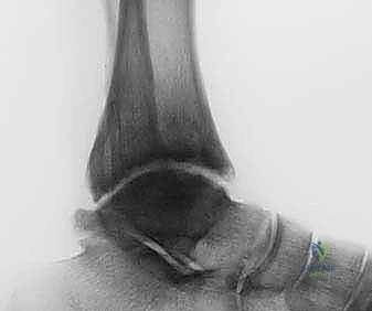
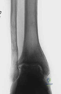
Thorough preoperative planning is the cornerstone of a successful external fixation procedure. The process begins with an exhaustive clinical examination, documenting the exact arc of motion, areas of point tenderness, neurovascular status, and the presence of any fixed contractures, particularly gastroc-soleus equinus. Radiographic evaluation must be comprehensive, initiating with standard weight-bearing anteroposterior (AP), lateral, and mortise views of the affected ankle, alongside AP and lateral weight-bearing views of the foot. These foundational images allow the surgeon to quantify joint space narrowing, identify osteophytes, and assess the overall morphology of the tibiotalar articulation.
Advanced radiographic views are indispensable for complex deformity analysis. The Hindfoot Alignment View (Saltzman view), obtained with a 20-degree angled radiolucent plate, is critical for visualizing the relationship between the tibial anatomical axis, the ankle joint, and the calcaneal tuberosity in a single plane, thereby quantifying hindfoot varus or valgus. A long axial view (non-weight-bearing) provides further insight into the subtalar joint and the parallelism between the calcaneal mid-body axis and the tibial mid-diaphyseal line. If diaphyseal deformities or limb-length discrepancies are suspected, full-length lower extremity AP and lateral radiographs are mandatory. Computed Tomography (CT) scans, ideally weight-bearing cone-beam CT, are increasingly utilized to map focal cartilage wear patterns, assess subchondral cyst morphology, and plan precise osteotomy trajectories.
Patient counseling must be brutally honest and comprehensive. The surgeon must set realistic expectations regarding the postoperative timeline, the inevitability of pin-site irritation, and the delayed nature of symptomatic relief (often taking 6 to 12 months post-frame removal to realize maximum benefit). Patients are routinely provided with detailed educational materials, visual aids of the external fixator, and, when possible, introduced to former patients who have successfully navigated the procedure. This peer-to-peer interaction is invaluable for demystifying the recovery process and establishing realistic psychological expectations.
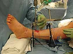
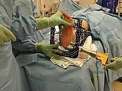
In the operating theater, meticulous patient positioning sets the stage for accurate frame application. The patient is positioned supine on a fully radiolucent operating table. A significant bump is placed beneath the ipsilateral hip to internally rotate the leg until the patella is oriented directly anteriorly, ensuring neutral rotation of the lower extremity relative to the floor. The entire leg, from the proximal thigh to the toes, is prepped and draped free. Sterile bath blankets or specialized sterile bumps are placed under the distal thigh and the foot, elevating the calf and allowing completely unencumbered access to the posterior aspect of the leg. This "floating" leg setup is absolutely essential for the unobstructed passage of full rings, precise wire tensioning, and the acquisition of perfect, orthogonal AP and lateral fluoroscopic images throughout the procedure.
Step-by-Step Surgical Approach and Fixation Technique
Deformity Correction and Joint Preparation
The surgical sequence commences with the correction of any extra-articular deformities or intra-articular pathology that would compromise the biomechanical integrity of the distracted joint. If the preoperative templating identified significant hindfoot varus or valgus, a calcaneal displacement osteotomy or subtalar arthrodesis is performed prior to frame application. Similarly, forefoot driven deformities, such as a rigid plantarflexed first ray, are addressed via dorsiflexion osteotomies or medial column fusions. Establishing a plantigrade, mechanically neutral foot is an absolute prerequisite; distracting an ankle that is subjected to asymmetric shear forces due to uncorrected malalignment will inevitably lead to failure.
For patients exhibiting significant anterior osteophytosis causing mechanical impingement, or those with loose bodies and severe synovitis, an open arthrotomy or arthroscopic débridement is performed. An anterior or medial arthrotomy allows for the meticulous resection of impinging osteophytes, thereby immediately improving the sagittal arc of motion. If medial deltoid ligament insufficiency is present, the ligament is imbricated and repaired with heavy non-absorbable sutures or suture anchors at this stage. Once the joint is mechanically optimized and the soft tissues are addressed, attention turns to the application of the external fixator.
Tibial Block Application
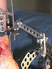
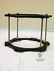
The tibial base frame serves as the rigid proximal anchor for the distraction construct. We typically utilize a Taylor Spatial Frame (TSF) or a traditional Ilizarov circular frame, selecting rings that provide a minimum of two fingerbreadths (approximately 2 to 3 cm) of circumferential soft tissue clearance to accommodate postoperative edema. The proximal block usually consists of two full rings connected by threaded rods. The distal ring of this block is positioned approximately 5 to 6 cm proximal to the ankle joint line. Positioning this ring too distally risks violating the joint capsule or tethering the anterior neurovascular bundle, while positioning it too proximally diminishes the mechanical control over the distal tibia.
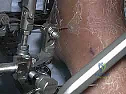
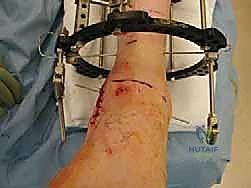
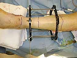
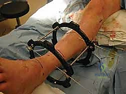
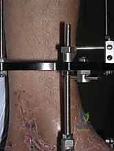
Frame application begins with the insertion of a smooth, 1.8-mm transverse reference wire on the distal tibial ring. This wire is inserted from medial to lateral, strictly orthogonal to the anatomical axis of the tibia in both the coronal and sagittal planes. Fluoroscopy is utilized to confirm that the wire passes safely anterior to the fibula and posterior to the anterior tibial crest. Once bicortical purchase is achieved, the wire is secured to the ring and tensioned to 130 kg using a dynamometer. A second wire, typically an olive wire inserted from anterolateral to posteromedial, is placed to provide multi-planar stability. This wire must carefully navigate between the anterior tibial neurovascular bundle and the superficial peroneal nerve. To augment the rigidity of the tibial block, two or three 5.0-mm or 6.0-mm hydroxyapatite-coated half-pins are inserted into the tibial diaphysis, utilizing a meticulous open technique with soft tissue sleeves to protect the neurovascular structures.
Foot Block Application and Hinge Placement
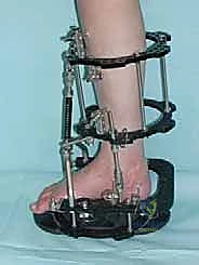
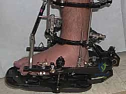
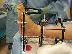
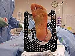
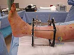
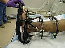
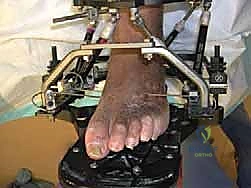
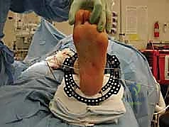
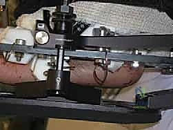
Following the stabilization of the tibial block, the foot block is constructed. This typically consists of a U-plate or a half-ring positioned parallel to the plantar aspect of the foot. Fixation is achieved using a combination of tensioned fine wires and half-pins. Two crossed olive wires are driven through the posterior tuberosity of the calcaneus, entering from medial and lateral to avoid the neurovascular bundle, and tensioned to 90-110 kg. Additional fixation is secured in the midfoot, often utilizing a transverse wire through the metatarsal bases or a half-pin inserted into the first cuneiform or cuboid, ensuring the entire foot acts as a single, rigid biomechanical unit.
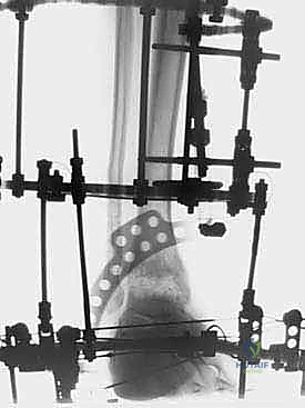
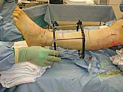
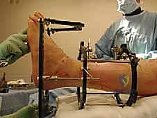
The critical juncture of the procedure is the connection of the tibial and foot blocks and the execution of the distraction. If a traditional Ilizarov construct is used, universal hinges are placed. The mechanical axis of these hinges must perfectly colocalize with the anatomical axis of rotation of the tibiotalar joint, which empirically passes through the tips of the medial and lateral malleoli. Misalignment of these hinges will result in eccentric loading, joint subluxation, and severe pain during motion. If a Taylor Spatial Frame is utilized, six multi-axial struts connect the tibial ring to the foot ring. The software program is then utilized to calculate the exact strut adjustments required to achieve pure, uniform axial distraction without inducing iatrogenic translation or angulation.
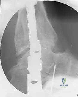
Executing the Joint Distraction
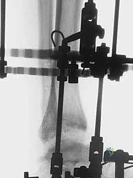
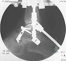
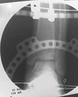
Distraction is typically performed acutely in the operating room under direct fluoroscopic visualization. The goal is to achieve a uniform, symmetric joint space of approximately 5 to 6 millimeters across the entire tibiotalar dome. The surgeon manually distracts the joint or adjusts the struts/threaded rods while continuously monitoring the joint space on true AP and mortise fluoroscopic views. It is imperative to ensure that the distraction is symmetric; asymmetric distraction indicates either unrecognized ligamentous tethering, bony impingement, or an improperly aligned frame vector.
Once the desired 5 mm distraction is achieved, the frame is locked. The foot is typically positioned in neutral dorsiflexion (0 degrees) to optimize the functional resting length of the Achilles tendon. If a severe preoperative equinus contracture was present, a percutaneous Achilles tendon lengthening (tendo-Achilles lengthening, TAL) or a gastrocnemius recession is performed simultaneously to relieve the tension on the posterior joint capsule and prevent the frame from inadvertently compressing the anterior joint space due to the powerful pull of the triceps surae.
Complications, Incidence Rates, and Salvage Management
While ankle distraction arthroplasty provides a powerful biological tool, it is an inherently demanding procedure associated with a distinct complication profile. The most ubiquitous complication is superficial pin tract infection, occurring in up to 80-90% of patients. These are typically classified using the Checketts-Otburn grading system. The vast majority are minor, presenting with localized erythema and serous drainage, and are exquisitely responsive to intensified local pin care (chlorhexidine or hydrogen peroxide solutions) and a short course of oral antibiotics (e.g., cephalexin or doxycycline). Deep infections or osteomyelitis are exceedingly rare (<2%) but demand immediate aggressive management, including pin removal, surgical debridement, and intravenous antibiotics.
Mechanical complications, including wire breakage, half-pin loosening, or frame failure, occur in approximately 5-10% of cases. These are often secondary to inadequate initial tensioning, poor bone quality, or patient non-compliance with weight-bearing restrictions. Wire breakage typically requires a return to the operating room for wire exchange to maintain the structural rigidity of the distraction construct. Iatrogenic neurovascular injury is a catastrophic but preventable complication, minimized by rigorous adherence to safe zones, the use of tissue protectors, and blunt dissection techniques. Transient neuropraxias, particularly of the superficial peroneal or sural nerves, may occur due to tensioning or postoperative edema but generally resolve spontaneously following frame removal.
Joint stiffness and persistent contracture represent significant clinical challenges. Despite the theoretical preservation of motion, the immobilization inherent in the rigid frame application can lead to capsular fibrosis. This underscores the critical importance of incorporating hinges (when using dynamic frames) and enforcing rigorous physical therapy immediately upon frame removal. If the procedure ultimately fails to provide adequate symptomatic relief—typically defined as persistent, debilitating pain 12 to 18 months post-frame removal—the joint is considered salvaged, and the patient is transitioned to the definitive end-stage options: ankle arthrodesis or total ankle arthroplasty. Notably, prior distraction does not preclude or complicate subsequent arthrodesis or replacement.
| Complication Type | Estimated Incidence | Preventative Strategy | Salvage / Management Protocol |
|---|---|---|---|
| Superficial Pin Tract Infection | 80 - 90% | Meticulous OR insertion technique; daily chlorhexidine pin care; avoiding skin tension. | Oral antibiotics (e.g., Cephalexin); intensified local cleaning; rarely requires pin removal. |
| Wire Breakage / Pin Loosening | 5 - 10% | Proper tensioning (130kg tibia, 90kg foot); bicortical purchase; rigid frame construct. | Return to OR for wire/pin exchange; augment frame stability; adjust weight-bearing. |
| Neurovascular Injury | < 2% | Strict adherence to safe zones; blunt dissection to periosteum; use of drill sleeves. | Immediate frame adjustment/pin removal if acute; neurolysis or vascular repair if severed (rare). |
| Deep Joint Infection / Osteomyelitis | < 1% | Avoiding intra-articular pin placement; aggressive treatment of superficial infections. | Immediate frame removal; aggressive surgical debridement; targeted IV antibiotics. |
| Persistent Joint Stiffness | 15 - 20% | Proper hinge alignment; dynamic frame protocols; aggressive post-removal PT. | Intensive physical therapy; manipulation under anesthesia; arthroscopic lysis of adhesions. |
Phased Post-Operative Rehabilitation Protocols
The postoperative rehabilitation protocol is as critical to the success of the procedure as the surgical execution itself. The rehabilitation is multiphasic, demanding high patient compliance and close coordination between the orthopedic surgeon and the physical therapy team.
Phase I: The Distraction Phase (Weeks 0-12)
Immediately postoperatively, the patient is admitted for pain control and initiation of pin-site care education. The frame remains locked in the distracted position (typically 5 mm of joint space) for a total duration of 10 to 12 weeks. Crucially, patients are encouraged to begin partial weight-bearing (approximately 30-50% of body weight) with crutches as soon as tolerated, usually within the first week. This intermittent axial loading is the mechanical trigger that drives the biological fluid pump, flushing the joint with synovial fluid and stimulating chondrocyte metabolism. Complete non-weight-bearing is counterproductive to the biological goals of the procedure. Daily pin-site care using a standardized protocol is mandatory to mitigate the high risk of superficial infections.
Phase II: Frame Removal and Early Mobilization (Weeks 12-16)
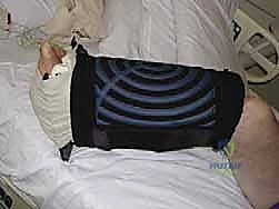
At the 10 to 12-week mark, radiographic confirmation of maintained joint space and stable bony alignment is obtained, and the external fixator is removed. This is typically performed in the clinic setting with oral analgesia or under light sedation in the operating room. Following removal, the limb is immediately placed in a controlled ankle motion (CAM) boot. Weight-bearing is transitioned to weight-bearing as tolerated in the boot. Physical therapy is initiated aggressively, focusing on active and active-assisted range of motion to combat the capsular stiffness that inevitably develops during the fixation period. Modalities to control edema, such as compression stockings and elevation, are critical during this phase.
Phase III: Strengthening and Return to Function (Months 4-12)
As the patient regains functional range of motion and pin sites fully epithelialize, the CAM boot is gradually weaned, and the patient transitions to supportive athletic footwear. Physical therapy shifts focus toward proprioceptive retraining, intrinsic
Clinical & Radiographic Imaging Archive