Radiographic Evaluation of Acetabular Fractures: Surgical Guide
Key Takeaway
Accurate radiographic evaluation of acetabular fractures is paramount for determining surgical indications and preoperative planning. This comprehensive guide details the interpretation of the anteroposterior pelvis and Judet oblique views, the application of Matta’s roof arc measurements, and the critical role of high-resolution computed tomography. Mastery of these imaging modalities allows orthopedic surgeons to accurately classify fracture patterns, assess articular congruity, and select the optimal surgical approach for anatomic restoration.
INTRODUCTION TO ACETABULAR IMAGING
The radiographic evaluation of the acetabulum is the cornerstone of diagnosing, classifying, and preoperatively planning the surgical management of acetabular fractures. Because the acetabulum is a complex, three-dimensional, cup-shaped structure housed within the pelvic ring, standard orthogonal imaging is insufficient to fully appreciate the "personality" of the fracture. The intricate spatial relationship between the anterior (iliopectineal) and posterior (ilioischial) columns requires a systematic, multi-modality imaging approach.
Historically pioneered by Judet and Letournel, the standard radiographic series remains the fundamental baseline for all acetabular trauma. However, modern operative orthopedics mandates the integration of high-resolution Computed Tomography (CT) to assess marginal impaction, intra-articular osteochondral fragments, and the precise geometry of comminution. This masterclass delineates the evidence-based protocols for radiographic evaluation, ensuring the orthopedic surgeon can accurately translate two-dimensional images into a three-dimensional surgical strategy.
THE STANDARD RADIOGRAPHIC SERIES
The initial evaluation of any suspected acetabular fracture begins with a standardized plain radiographic series. This consists of an Anteroposterior (AP) view of the pelvis and two 45-degree oblique views, universally known as the Judet views.
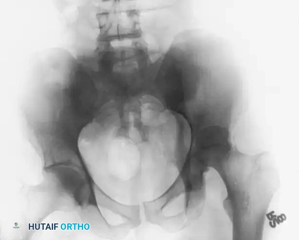
The Anteroposterior (AP) Pelvis View
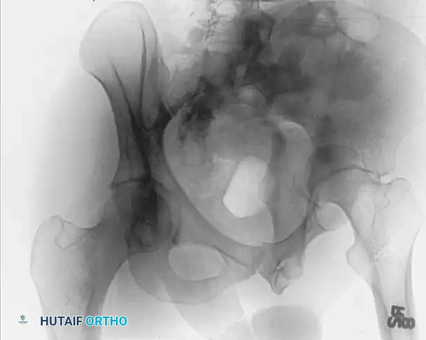
The AP pelvis view provides a panoramic assessment of the pelvic ring and bilateral acetabula. Inclusion of the opposite, uninjured hip in the radiographic field is essential. This allows the surgeon to evaluate symmetrical contours, account for slight individual anatomical variations, and determine the baseline width of the normal articular cartilage space.
When evaluating the AP view, the surgeon must systematically trace the six fundamental radiographic landmarks of Letournel:
1. The Iliopectineal Line: Represents the anterior column.
2. The Ilioischial Line: Represents the posterior column.
3. The Radiographic Teardrop: Represents the medial wall of the acetabulum. The lateral limb is the inferior aspect of the acetabular fossa, and the medial limb is the quadrilateral surface.
4. The Acetabular Roof (Dome): The superior weight-bearing articular surface.
5. The Anterior Lip (Wall): The anterior margin of the articular surface.
6. The Posterior Lip (Wall): The posterior margin of the articular surface.
Clinical Pearl: The medial clear space between the femoral head and the radiographic teardrop must be meticulously compared between the injured and uninjured hips. Asymmetry or widening on the AP view is a highly sensitive indicator of lateral femoral head subluxation or interposition of intra-articular fragments.
The Judet Oblique Views
To isolate the anterior and posterior columns, Judet and Letournel described two 45-degree oblique views. These are obtained by rolling the patient 45 degrees relative to the X-ray cassette.
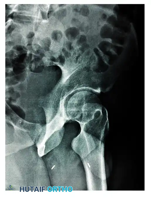
The Iliac Oblique View
In the iliac oblique view, the patient is rolled 45 degrees toward the uninjured side (elevating the injured hip). The radiographic beam is directed roughly perpendicular to the iliac wing of the affected side.
* Primary Structures Visualized: This view places the iliac wing en face, providing an excellent profile of the posterior column and the anterior wall of the acetabulum.
* Diagnostic Utility: It is critical for identifying fractures traversing the sciatic notch, assessing the integrity of the posterior column, and evaluating anterior wall comminution.
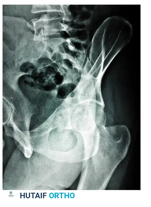
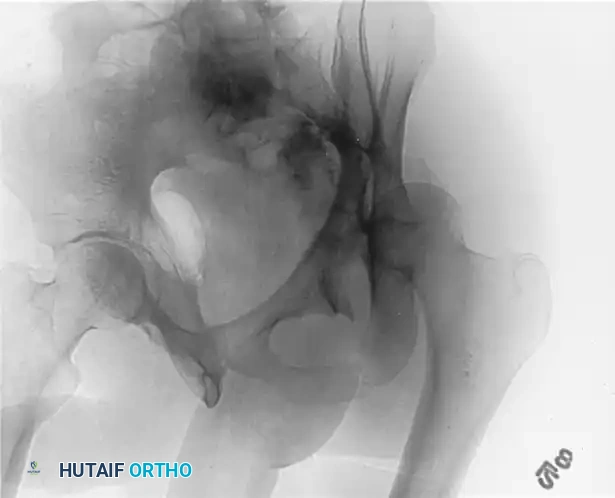
The Obturator Oblique View
In the obturator oblique view, the patient is rolled 45 degrees toward the injured side (elevating the uninjured hip). The radiographic beam is directed roughly perpendicular to the obturator foramen of the affected side.
* Primary Structures Visualized: This view places the obturator ring en face, providing a true profile of the anterior column and the posterior wall of the acetabulum.
* Diagnostic Utility: It is the definitive view for assessing the iliopectineal line's distal extent, the obturator ring, and the size and displacement of posterior wall fracture fragments.
QUANTIFYING THE ACETABULAR DOME: ROOF ARC MEASUREMENTS
Fractures that traverse the acetabular dome (roof) can be visualized on the AP and Judet views. However, the subchondral bone shown on these plain radiographs is only 2 to 3 mm wide, representing only a small, tangential portion of the actual weight-bearing articular surface.
To determine whether a fracture compromises the critical weight-bearing dome enough to warrant surgical fixation, Matta et al. developed a standardized system known as the "Roof Arc" measurements. These measurements quantify how much of the superior articular surface remains intact and attached to the axial skeleton.
Technique for Measuring Roof Arcs
The roof arc is measured across the three standard radiographic views. A vertical reference line is drawn through the geometric center of the acetabulum. A second line is drawn from the geometric center to the point where the fracture line intersects the intact acetabular roof. The angle formed between these two lines is the roof arc.
- Medial Roof Arc: Measured on the AP pelvis view. Evaluates the superior-medial aspect of the dome.
- Anterior Roof Arc: Measured on the Obturator Oblique view. Evaluates the superior-anterior aspect of the dome.
- Posterior Roof Arc: Measured on the Iliac Oblique view. Evaluates the superior-posterior aspect of the dome.
Surgical Indication Warning: According to the biomechanical principles established by Matta et al., if any of the three roof arc measurements in a displaced fracture are less than 45 degrees, the critical weight-bearing dome is compromised, and operative treatment (ORIF) should be strongly considered to prevent rapid post-traumatic arthrosis.

While roof arc measurements provide excellent quantitative data for transverse, T-type, and associated anterior column/posterior hemitransverse fractures, they have limited utility in evaluating both-column fractures (where no portion of the roof remains attached to the intact ilium) or isolated posterior wall fractures.
ADVANCED IMAGING: COMPUTED TOMOGRAPHY (CT)
While plain radiographs provide the foundational classification, Computed Tomography (CT) is invaluable and mandatory in the modern treatment of acetabular fractures. CT defines the precise location of fracture lines, the degree of comminution, the presence of marginal impaction, and the existence of intra-articular loose bodies.
CT Imaging Protocols
Axial cuts must be obtained at thin intervals (maximum 2 to 3 mm slice thickness) to ensure small osteochondral fragments are not missed. The entire pelvis, from the iliac crests to the lesser trochanters, must be included to avoid missing proximal fracture extensions or associated pelvic ring injuries. Comparison to the opposite, uninjured hip is performed routinely.
Interpreting the Axial CT Scan
The surgeon must develop the cognitive skill to scroll from image to image (proximal to distal), following the fracture lines and mentally reconstructing the 3D obliquities and displacements.
* Sagittal Plane Fractures: Transverse fracture lines and fractures of the anterior and posterior walls typically orient in the sagittal plane, paralleling the quadrilateral surface when viewed on axial CT images.
* Coronal Plane Fractures: Anterior and posterior column fractures usually extend through the quadrilateral surface and into the obturator foramen with a more coronal orientation.
Pitfall Avoidance: Novice surgeons often believe that axial CT images overestimate comminution. In reality, CT only displays existing fracture lines. For example, in a transverse fracture, moving proximally on successive cuts will show small fragments of the anterior and posterior walls enlarging and coalescing through the roof to become the intact axial cross-section of the ilium. What appears as separate wall fragments inferiorly is actually the distal extent of a single proximal fragment.
The "10-mm Rule" of the Acetabular Dome
CT scans provide highly accurate information regarding the integrity of the acetabular dome, directly correlating with Matta's plain radiographic roof arc measurements.
Biomechanical studies have demonstrated that if the superior 10 mm of the acetabular roof is intact on axial CT scans, it corresponds to a radiographic roof arc measurement of at least 45 degrees. Furthermore, fractures involving the cotyloid fossa do not jeopardize the stability of the femoral head, provided the fracture extends no closer than 10 mm to the apex of the roof and the superior articular surface remains intact.
Multiplanar and 3D Reconstructions
High-resolution coronal and sagittal reconstructions are critical for preoperative planning. They delineate fracture lines that lie parallel to the axial plane (which might be obscured on standard axial cuts) and provide a clear view of the dome's congruity.
Three-dimensional (3D) CT reconstructions have become highly sophisticated. The ability to digitally subtract the femoral head allows the surgeon to look directly into the acetabular cup, revealing the unique topographical features of the fracture pattern. While axial, coronal, and sagittal cuts remain the gold standard for assessing articular step-offs, 3D reconstructions are exceptional tools for understanding the overall spatial geometry and planning plate contouring.
RADIOGRAPHIC FRACTURE PATTERN RECOGNITION
Utilizing the Letournel classification, acetabular fractures are divided into five elementary and five associated patterns. Radiographic evaluation is the sole method for accurate classification, which in turn dictates the surgical approach.
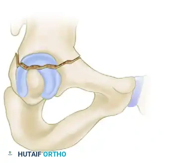
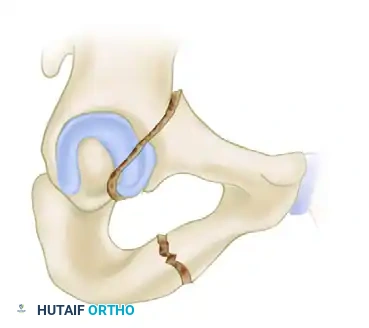
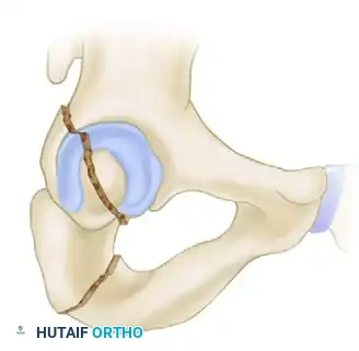
Example: Posterior Column Fracture
A classic elementary fracture is the isolated posterior column fracture. Radiographic evaluation will reveal specific disruptions:
* AP View: Shows an intact iliopectineal line (anterior column) with a disrupted ilioischial line (posterior column).
* Iliac Oblique View: Shows the disrupted posterior column in profile, while the anterior wall remains intact.
* Obturator Oblique View: Shows the intact anterior column and obturator ring in profile.
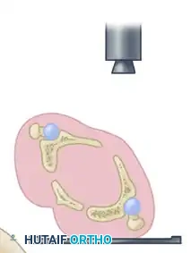
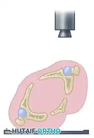
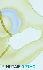
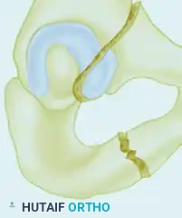
The "Spur Sign" in Both-Column Fractures
Associated fracture types possess complex geometries, including T-type, combined transverse and posterior wall, and both-column fractures.
The designation of a both-column fracture implies a complete dissociation of the articular surface from the axial skeleton. A fracture line divides the ilium such that the sacroiliac joint is no longer connected to any articular segment of the acetabulum.
The radiographic hallmark of a both-column fracture is the Spur Sign, best visualized on the obturator oblique view. The spur represents the lowermost portion of the intact intact ilium (strut of bone extending from the sacroiliac joint) that has been left behind as the entire articular segment is displaced medially and distally. Identifying the spur sign is pathognomonic for a both-column variant and immediately alerts the surgeon to the need for a complex, often anterior or extensile, surgical approach.
PREOPERATIVE PLANNING AND SURGICAL APPROACH SELECTION
The ultimate goal of radiographic evaluation is to formulate a definitive preoperative plan. The fracture pattern identified on X-ray and CT dictates patient positioning and the surgical approach.
- Posterior Approaches (Kocher-Langenbeck): Indicated for posterior wall, posterior column, and certain transverse or T-type fractures where the major displacement is posterior. The imaging must confirm that the anterior column is either intact or minimally displaced.
- Anterior Approaches (Ilioinguinal or Stoppa): Indicated for anterior wall, anterior column, anterior column posterior hemitransverse, and many both-column fractures. CT evaluation of the quadrilateral plate is critical here; severe medial displacement often requires a Stoppa approach for direct buttressing.
- Extensile Approaches (Iliofemoral): Reserved for complex associated patterns with severe comminution of both columns that cannot be reduced indirectly from a single approach.
During planning, the surgeon should utilize a plastic pelvic model. By drawing the fracture lines identified on the CT scan directly onto the model, the surgeon can simulate the reduction sequence, anticipate the trajectory of lag screws, and pre-contour reconstruction plates.
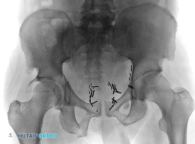
POSTOPERATIVE RADIOGRAPHIC PROTOCOLS
Following Open Reduction and Internal Fixation (ORIF), postoperative radiographic evaluation is utilized to assess the quality of the articular reduction and the placement of hardware.
Standard postoperative imaging includes a repeat AP pelvis and bilateral Judet views. The quality of reduction is graded according to Matta's criteria based on the maximum residual displacement (step-off or gap) measured on any of the three plain radiographic views:
* Anatomic: 0 to 1 mm of displacement.
* Imperfect: 2 to 3 mm of displacement.
* Poor: Greater than 3 mm of displacement.
Postoperative CT scanning is increasingly utilized to rule out intra-articular hardware penetration and to provide a highly accurate assessment of the articular reduction, as plain radiographs may underestimate residual step-offs. Achieving an anatomic reduction (≤1 mm) is the single most important surgeon-controlled variable in preventing post-traumatic osteoarthritis and ensuring long-term survivorship of the native hip joint.
You Might Also Like