Mastering Posterior Screw Fixation for Sacral Fractures and Sacroiliac Dislocations
Key Takeaway
Posterior screw fixation is a cornerstone technique for stabilizing sacral fractures and sacroiliac joint disruptions. This procedure demands a profound understanding of upper sacral morphology, specifically the sacral alar slope and the iliac cortical density (ICD). Utilizing precise fluoroscopic imaging—including inlet, outlet, and true lateral views—surgeons can safely navigate the osseous corridor, avoiding critical neurovascular structures such as the L5 nerve root and iliac vessels.
Introduction to Posterior Pelvic Ring Fixation
The posterior pelvic ring is the primary weight-bearing axis of the human pelvis, transmitting forces from the axial skeleton to the lower extremities. Disruptions of this complex—whether through sacral fractures, sacroiliac (SI) joint dislocations, or fracture-dislocations—severely compromise pelvic stability and demand robust mechanical fixation.
Posterior screw fixation, specifically iliosacral screw insertion, has become the gold standard for stabilizing these injuries. Pioneered by Matta and Saucedo for open techniques and later refined by Routt et al. for percutaneous applications, this procedure requires an exacting knowledge of tridimensional pelvic anatomy, advanced fluoroscopic interpretation, and precise surgical execution.
This comprehensive guide details the indications, biomechanics, radiographic planning, and step-by-step surgical techniques for posterior screw fixation of the pelvic ring, encompassing both open and percutaneous methodologies.
Surgical Anatomy and Biomechanics
The upper sacrum presents a highly variable and complex tridimensional morphology. Safe placement of an iliosacral screw requires navigating a narrow osseous corridor—the "safe zone"—within the S1 (and occasionally S2) vertebral body.
The Sacral Alar Slope and Safe Zone
The normal sacral ala features an inclined anterosuperior surface known as the sacral alar slope, which extends from proximal-posterior to distal-anterior.
Surgical Warning: The cortex of the alar slope forms the absolute anterior boundary of the safe zone for the passage of iliosacral screws into the S1 body. Anterior to this slope lie the L5 nerve root and the iliac vessels. Penetration of this cortex can result in catastrophic hemorrhage or permanent iatrogenic neurologic deficit.
The posterior boundary of the safe zone is formed by the anterior cortex of the S1 nerve root foramen. Therefore, the screw must be placed perfectly between the alar slope anteriorly and the neuroforamen posteriorly.
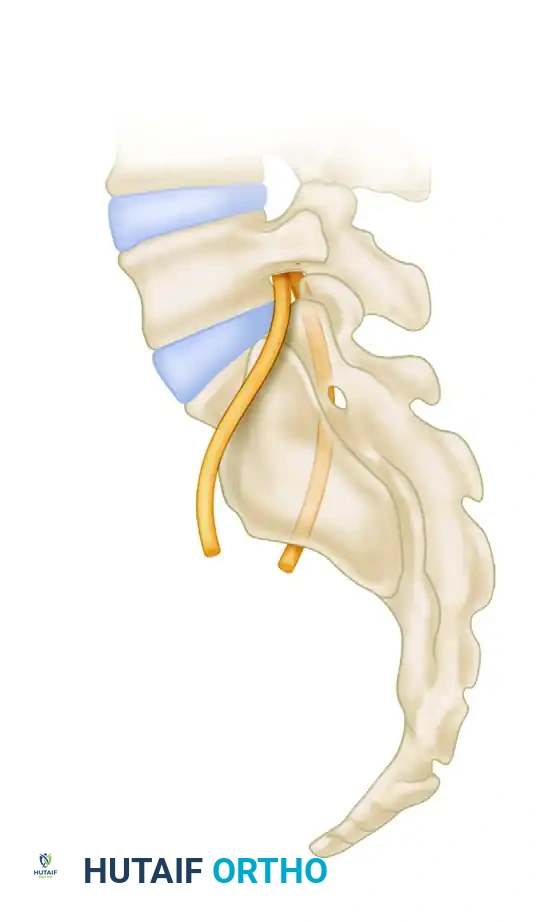
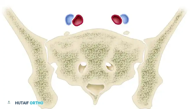
Anatomical relationship of the fifth lumbar (L5) and intraosseous first sacral (S1) nerve roots with the sacral ala.
Sacral Dysplasia and Morphological Variations
A thorough evaluation of upper sacral morphological features is mandatory. Routt et al. demonstrated that sacral dysplasia occurs in a significant percentage of patients (up to 35% in some series). A dysplastic sacrum typically exhibits an atypical, more acute sacral alar slope and a constricted osseous corridor, drastically narrowing the safe zone.
Variable structure of the upper sacrum as visualized on outlet views, highlighting the Iliac Cortical Density (ICD).
Furthermore, some non-dysplastic sacral alae display an anterior concavity or recession when viewed in the axial plane. A recessed sacral ala creates a dangerous anatomical trap, allowing for an "in-out-in" screw trajectory that inadvertently exits the anterior sacral cortex and re-enters the vertebral body, directly threatening the L5 nerve root.
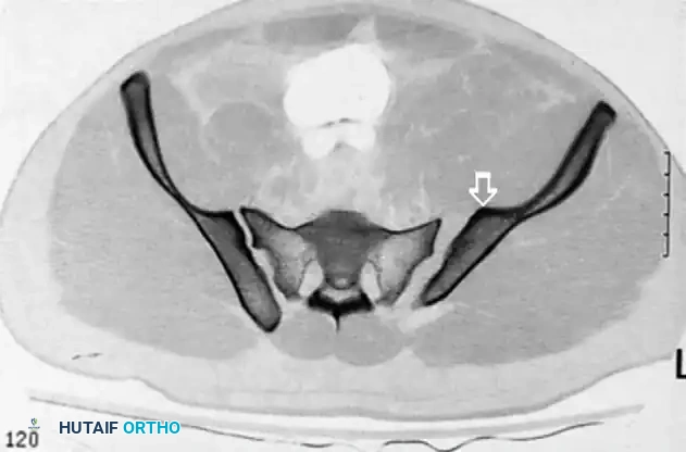
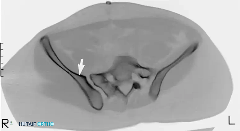
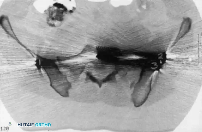
CT scan demonstrating a recessed sacral ala (solid arrows) relative to the dense iliac bone adjacent to the sacroiliac joint—the iliac cortical density (ICD) (open arrow). Nerve roots are surrounded by fat within these recessed alae.
Preoperative Radiographic Evaluation
Standard anteroposterior (AP) pelvic radiographs are insufficient for planning iliosacral screw fixation. A complete radiographic series, supplemented by fine-cut Computed Tomography (CT), is essential.
The Iliac Cortical Density (ICD)
The sacral alar slope can be estimated on a true lateral fluoroscopic view of the sacrum by identifying the Iliac Cortical Density (ICD). The ICD demarcates the anterior cortical thickening of the iliac portion of the sacroiliac joint.
In the vast majority (approx. 94%) of non-dysplastic upper sacral segments, the ICD coincides perfectly with the alar slope, making it an invaluable radiographic landmark for determining the anterior border of the safe zone during surgery.
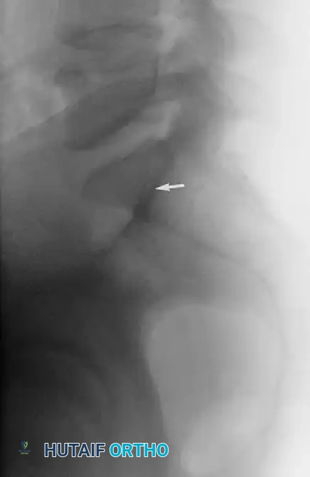
The Iliac Cortical Density (ICD) identified on a lateral radiograph for estimation of the sacral alar slope.
Diagrammatic representation of variable alar slopes and their relationship to the ICD.
Computed Tomography (CT) Planning
Preoperative CT with axial, coronal, and sagittal reformats is critical to:
1. Determine the exact dimensions of the S1 and S2 safe zones.
2. Identify sacral dysplasia or transitional lumbosacral vertebrae.
3. Detect recessed sacral alae that preclude standard screw trajectories.
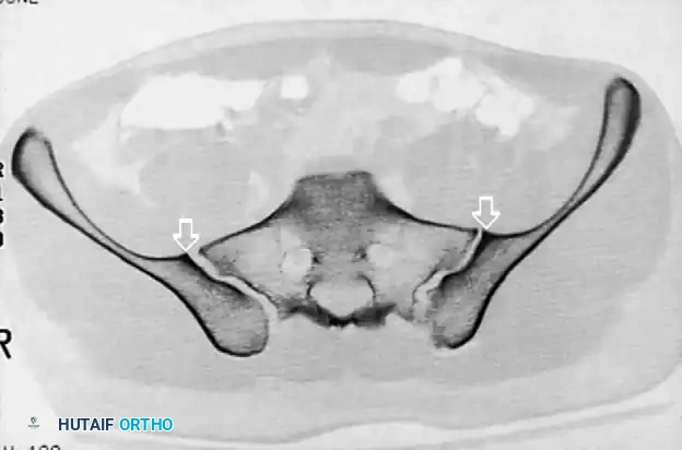
CT scan confirming a narrow safe zone resulting from a dysplastic upper sacral segment. The anterior articular surfaces of the sacroiliac articulations are planar bilaterally.
Patient Positioning and Operating Room Setup
Proper positioning is the foundation of successful posterior pelvic fixation. The procedure can be performed with the patient supine or prone, depending on surgeon preference, associated injuries (e.g., anterior ring fractures requiring simultaneous fixation), and the planned approach (open vs. percutaneous).
Prone Positioning (Matta and Saucedo Technique)
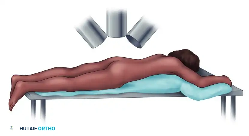
- Position the patient prone on a completely radiolucent operating table.
- Ensure the abdomen is free from compression to reduce venous pressure and minimize epidural bleeding.
- Pad all bony prominences meticulously.
Patient positioning prone on a radiolucent board to allow unobstructed fluoroscopic imaging.
Fluoroscopic Setup
The image intensifier (C-arm) must be able to freely rotate to obtain three critical views without moving the patient:
1. Inlet View: C-arm tilted 25 to 40 degrees caudad. Evaluates AP translation and the anterior/posterior boundaries of the sacral body.
2. Outlet View: C-arm tilted 40 degrees cephalad. Evaluates vertical displacement and the superior/inferior boundaries of the S1 safe zone (neural foramina).
3. True Lateral View: Evaluates the alar slope and ICD.
C-arm positioning demonstrating 40 degrees cephalad (Outlet) and 40 degrees caudad (Inlet) projections to guide drill bit and screw position.
Surgical Technique: Open Posterior Approach
The open approach, as described by Matta and Saucedo, is indicated when closed reduction of a sacroiliac dislocation or sacral fracture is unachievable, or when direct decompression of sacral nerve roots is required.
1. Incision and Exposure
- Make a standard posterior vertical incision, located approximately 2 cm lateral to the posterior superior iliac spine (PSIS).
- Incise the subcutaneous tissues down to the gluteal fascia.
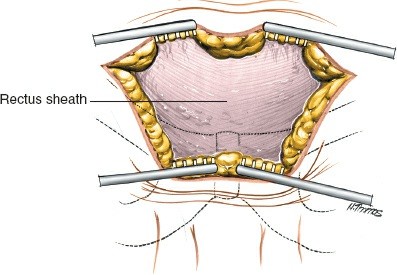
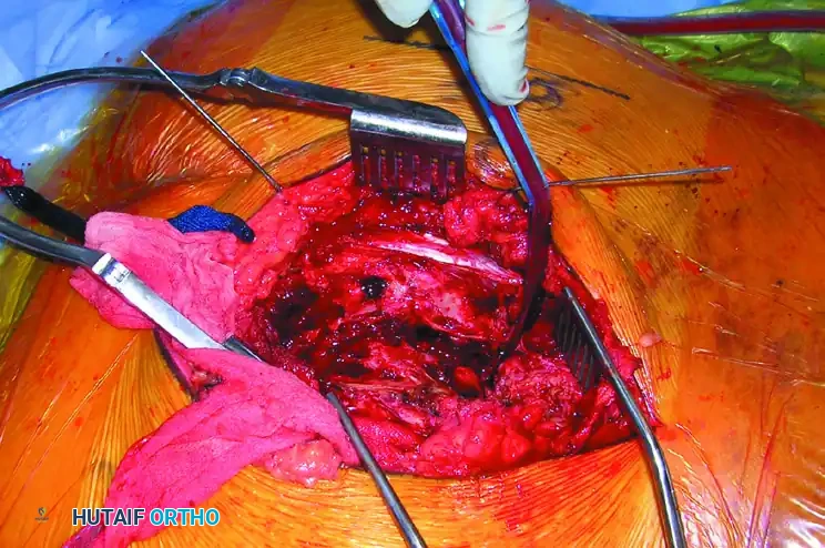
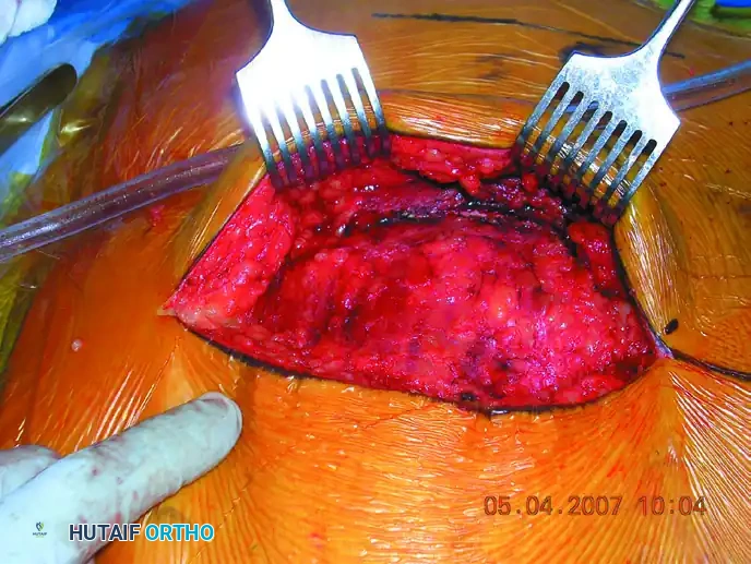
Initial open exposure of the posterior ilium and sacroiliac region.
- Reflect the posterior portion of the gluteal muscles from the posterior iliac wing.
- Detach the origin of the gluteus maximus from the sacrum to expose the posterior sacroiliac ligaments.
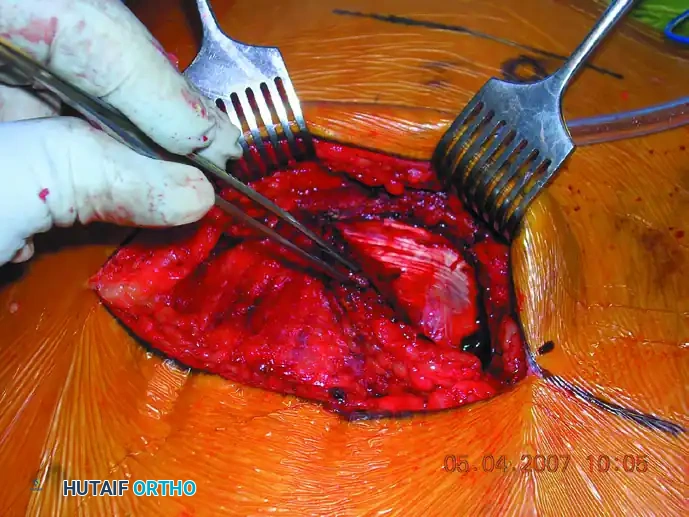
Deep exposure reflecting the gluteal musculature to visualize the posterior sacral lamina and greater sciatic notch.
2. Joint Evaluation and Reduction
- Expose the greater sciatic notch. This is a critical step to digitally palpate and evaluate the accuracy of the reduction at the anterior aspect of the SI joint.
- For sacral fractures, elevate the multifidus muscles to expose the fracture of the posterior sacral lamina.
- Reduction Maneuver: For sacroiliac dislocations, place pointed Weber or Jungbluth reduction forceps from the sacrum (via a drill hole in the posterior iliac spine) to the iliac wing.
- Compress the joint while palpating through the greater sciatic notch and directly observing the posterior joint line to confirm anatomic reduction.
3. Screw Insertion
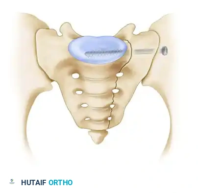
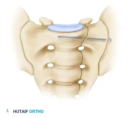
- Under continuous image intensifier control, insert a guide wire perpendicular to the iliac wing, directing it across the sacroiliac joint into the sacral ala, targeting the center of the S1 vertebral body.
Surgical diagram illustrating the trajectory of the iliosacral screw crossing the SI joint into the S1 body.
- Carefully target the drill bit and subsequent screws by alternating between AP, inlet, outlet, and lateral fluoroscopic projections.
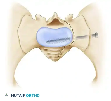
- Insert one or two fully threaded or partially threaded 7.0 mm or 7.3 mm cannulated screws into the S1 vertebral body from the lateral surface of the iliac wing.
Cross-sectional diagram showing optimal screw placement within the S1 osseous corridor.
Clinical Pearl: Screws used to fix sacroiliac joint disruptions are placed perpendicular to the joint to maximize compression. Conversely, screws used to fix transforaminal sacral fractures are placed more transversely to allow passage of the screw deep into the contralateral ala, maximizing thread purchase in dense bone.
4. Supplemental Fixation and Closure
- If comminution or instability persists, apply a 3.5-mm or 4.5-mm reconstruction plate across the posterior sacrum from ilium to ilium as a tension band, positioned just superior to the greater sciatic notch.
- Thoroughly irrigate the wound.
- Suture the gluteal fascia securely to the sacral spine.
- Close the subcutaneous tissues and skin in a standard layered manner over closed suction drains to prevent postoperative hematoma.
Surgical Technique: Percutaneous Iliosacral Screw Fixation
Percutaneous fixation, extensively developed by Routt et al., minimizes soft tissue stripping, reduces blood loss, and lowers infection rates. It relies entirely on flawless fluoroscopic imaging.
1. Closed Reduction
- The posterior pelvis must be accurately reduced prior to any drilling. Malreduction distorts radiographic landmarks, making the superimposition of the greater sciatic notches and both ICDs on the true lateral image impossible.
- Reduction is achieved via skeletal traction, pelvic binders, or percutaneous joy-sticks (Schanz pins placed in the iliac crests).
2. Fluoroscopic Targeting
- Obtain a perfect true lateral view of the sacrum. The greater sciatic notches must be perfectly superimposed.
- Identify the ICD. The guide wire starting point is mapped on the lateral ilium.
- Advance the guide wire through the ilium and into the sacral ala.
- Switch to Inlet View: Confirm the wire is posterior to the anterior sacral cortex and anterior to the spinal canal.
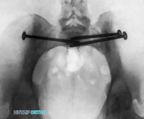
Inlet pelvic radiograph demonstrating correct anterior-posterior trajectory of the guide wires and screws.
Alternative inlet view confirming intraosseous placement of bilateral iliosacral screws.
- Switch to Outlet View: Confirm the wire is superior to the S1 neuroforamen and inferior to the S1 superior endplate.
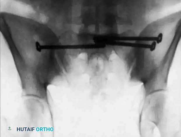
Outlet pelvic radiograph confirming screws are safely positioned above the S1 neural foramina.
3. Drilling and Screw Placement
- Once the guide wire is confirmed to be entirely intraosseous in all three planes, advance the cannulated drill bit over the wire.
- Measure the depth, tap the near cortex if necessary, and insert the appropriate length cannulated screw (typically 7.0 mm or 7.3 mm). Washers are highly recommended to prevent the screw head from sinking into the thin iliac cortex.
Complications and Pitfalls
The most devastating complication of iliosacral screw fixation is iatrogenic nerve injury, most commonly affecting the L5 or S1 nerve roots.
The "In-Out-In" Phenomenon
If the surgeon fails to recognize a recessed sacral ala or relies solely on inlet and outlet views without a true lateral view referencing the ICD, the screw may exit the anterior cortex of the sacrum and re-enter the vertebral body. This extraosseous trajectory directly impales or compresses the L5 nerve root.
Postoperative CT scan showing a catastrophic "in-out-in" error. The cephalad anterior iliosacral screw on the patient’s left side is extraosseous, resulting in a severe left L5 nerve root injury.
Surgical Warning: Never advance a drill or screw if the guide wire trajectory cannot be definitively confirmed in the Inlet, Outlet, AND True Lateral planes. If visualization is obscured by bowel gas or obesity, the procedure must be converted to an open approach or alternative fixation (e.g., posterior tension band plating) must be utilized.
Fixation Failure
Failure of fixation can occur due to unrecognized comminution, severe osteoporosis, or inadequate screw length. In cases of vertical shear instability, a single S1 screw is often insufficient; bi-segmental fixation (screws in both S1 and S2) or supplemental lumbopelvic fixation may be required.
Postoperative Protocol
- Weight-Bearing: Patients are typically restricted to toe-touch or non-weight-bearing on the affected side for 6 to 12 weeks, depending on the fracture pattern and bone quality.
- DVT Prophylaxis: Pelvic trauma carries a high risk of deep vein thrombosis. Chemical prophylaxis (e.g., LMWH) should be initiated as soon as it is surgically safe.
- Radiographic Follow-up: AP, inlet, and outlet radiographs are obtained immediately postoperatively, at 2 weeks, 6 weeks, and 12 weeks to monitor for loss of reduction or hardware migration. CT scanning may be utilized postoperatively if there is any clinical suspicion of neurologic irritation.
By adhering strictly to anatomical landmarks, respecting the boundaries of the sacral safe zones, and demanding perfect fluoroscopic imaging, the orthopedic surgeon can execute posterior screw fixation with high efficacy and minimal morbidity.
You Might Also Like