Navigated Total Knee Arthroplasty: An Intraoperative Masterclass
Key Takeaway
Precision in total knee arthroplasty is paramount for implant longevity. This masterclass delves into navigated TKA, emphasizing accurate component positioning and limb alignment. We'll explore preoperative planning, meticulous patient positioning, and the granular steps of intraoperative registration, ensuring optimal biomechanics and mitigating common pitfalls. Understand how real-time feedback guides critical decisions, enhancing surgical precision and improving long-term patient outcomes.
Comprehensive Introduction and Patho-Epidemiology
The evolution of Total Knee Arthroplasty (TKA) represents one of the most successful interventions in modern orthopedic surgery, yet the pursuit of the "perfect" knee remains an ongoing academic and clinical endeavor. Historically, conventional TKA relied heavily on intramedullary and extramedullary alignment guides. While these mechanical jigs have served the orthopedic community well, they are inherently subject to anatomical variations, user error, and static assumptions about dynamic joint function. The literature consistently demonstrates that conventional instrumentation results in alignment outliers (defined as >3 degrees deviation from the neutral mechanical axis) in approximately 20% to 30% of cases. This is not merely an academic triviality; errors as small as three degrees in coronal alignment or component rotation significantly alter the biomechanical load distribution across the polyethylene bearing, exponentially increasing the risk of accelerated wear, aseptic loosening, and early catastrophic implant failure.
The patho-epidemiology of TKA failure has shifted over the past two decades. While infection and instability remain prominent, aseptic loosening secondary to malalignment and subsequent particulate debris-induced osteolysis continues to be a primary driver of late revisions. Furthermore, isolated patellofemoral complications, often manifesting as intractable postoperative anterior knee pain or patellar maltracking, are frequently traced back to subtle errors in femoral or tibial component internal rotation. The imperative of precision in modern arthroplasty cannot be overstated, particularly as our patient demographic trends younger, heavier, and more active. These patients place unprecedented cyclic demands on their prostheses, demanding a surgical execution that leaves zero margin for macroscopic error.
Enter computer-assisted orthopedic surgery (CAOS), specifically navigated TKA. This intraoperative adjunct fundamentally transforms the procedure from a static, anatomically assumed operation into a dynamic, patient-specific kinematic reconstruction. Navigation provides the surgeon with real-time, objective, three-dimensional spatial data regarding limb alignment, component positioning, and, critically, soft-tissue gap balancing throughout the entire arc of motion. By digitizing the patient's unique osteology and ligamentous tension, the surgeon is empowered to make micro-adjustments prior to committing to irreversible bone resections. This "measure twice, cut once" philosophy, augmented by infrared optical tracking, mitigates the variability inherent in manual instrumentation.
Today, the paradigm of TKA alignment is actively debated, with philosophies ranging from strict mechanical alignment (MA) to kinematic alignment (KA) and restricted kinematic alignment (rKA). Regardless of the surgeon's philosophical alignment target, navigation serves as the ultimate execution tool. It allows for the precise recreation of the native joint line obliquity and the exact matching of flexion and extension gaps, minimizing the need for extensive, non-physiologic soft-tissue releases. This masterclass chapter will dissect the navigated TKA process, providing an exhaustive, step-by-step technical guide to mastering this indispensable technology in the operating theater.
Detailed Surgical Anatomy and Biomechanics
A profound, three-dimensional understanding of knee osteology, soft-tissue envelopes, and dynamic biomechanics is the absolute prerequisite for successful navigated TKA. The navigation system is only as accurate as the anatomical landmarks digitized by the surgeon; thus, a "garbage in, garbage out" principle strictly applies. Osteologically, the distal femur and proximal tibia present highly complex geometries. On the femur, the critical landmarks include the deepest part of the trochlear groove, the medial and lateral prominences of the distal and posterior condyles, and the surgical transepicondylar axis (sTEA). The sTEA, defined by the prominence of the lateral epicondyle and the sulcus of the medial epicondyle, is the functional axis of knee flexion and the gold standard for setting femoral component rotation.
The proximal tibia requires equally meticulous identification. The mechanical axis of the tibia is defined by the center of the tibial plateau proximally and the center of the talus distally. Rotational alignment on the tibia is classically referenced using Akagi’s line (from the middle of the posterior cruciate ligament insertion to the medial third of the tibial tubercle) or the medial third of the tibial tubercle itself. Navigation systems require the surgeon to map these points with a sterile probe. Errors in digitizing the malleoli, for instance, will directly skew the calculated tibial mechanical axis, leading to an erroneous varus or valgus resection. Therefore, percutaneous palpation or dynamic registration of the ankle center must be executed with exacting precision.
The muscular and neurovascular anatomy dictates our surgical approach and risk mitigation strategies. The standard medial parapatellar arthrotomy exploits the interval between the vastus medialis obliquus (VMO) and the quadriceps tendon. While exposing the joint, the surgeon must remain acutely aware of the posterior neurovascular bundle. The popliteal artery is tethered at the soleal arch and the adductor hiatus, making it particularly vulnerable during aggressive posterior capsular releases or if the tibial resection is excessively deep and posterior. The common peroneal nerve, wrapping around the fibular neck, is at extreme risk during the correction of severe valgus deformities where lateral structures (e.g., iliotibial band, posterolateral capsule) are tight and require release.
Biomechanically, the native knee is not a simple hinge but a complex, polycentric joint governed by the cam-and-post interaction of the cruciate ligaments and the topography of the articular surfaces. As the knee flexes, the femur undergoes coupled external rotation and posterior translation (femoral rollback) on the tibia, maximizing clearance for deep flexion and optimizing the extensor mechanism's moment arm. The "screw-home" mechanism locks the knee in terminal extension via internal rotation of the femur. Navigated TKA aims to restore these kinematics by ensuring the joint line is neither elevated nor depressed and that the flexion and extension gaps are perfectly symmetric. By providing real-time data on ligamentous tension before any bone is cut, navigation allows the surgeon to balance the knee dynamically, rather than relying on static, post-resection spacer blocks.
Exhaustive Indications and Contraindications
While computer-assisted navigation can be utilized in primary, routine TKA to ensure precision, its utility becomes exponentially more critical in complex anatomical scenarios where conventional instrumentation is either highly inaccurate or physically impossible to deploy. The decision to employ navigation should be tailored to the patient's specific pathoanatomy, the surgeon's experience, and the availability of the technology. Below is an exhaustive breakdown of the indications and contraindications for navigated TKA.
The most absolute indication for navigated TKA is the presence of extra-articular deformity. Patients with prior femoral or tibial shaft fractures treated with intramedullary nails, or those with malunions resulting in significant coronal or sagittal bowing, present a unique challenge. Conventional TKA relies on an intramedullary rod placed up the femoral canal to set the distal femoral valgus cut angle. If the canal is obstructed by hardware or deformed by a malunion, the intramedullary guide cannot be used, or worse, will dictate an entirely incorrect resection angle. Navigation circumvents this entirely by utilizing an extramedullary, optical reference frame, allowing the surgeon to calculate the true mechanical axis independently of the diaphyseal anatomy.
Another strong indication is severe obesity. In morbidly obese patients, identifying external anatomical landmarks (such as the center of the femoral head or the center of the ankle) for conventional extramedullary tibial guides is fraught with error due to the thick adipose envelope. Navigation systems that utilize dynamic kinematic registration—calculating the hip center of rotation by moving the femur through a circumduction arc—eliminate the need for external palpation, drastically reducing alignment outliers in this challenging demographic.
| Category | Specific Conditions | Rationale / Clinical Note |
|---|---|---|
| Primary Indications | Retained Intramedullary Hardware | Precludes the use of standard IM femoral alignment guides. |
| Extra-articular Malunion/Deformity | Diaphyseal bowing invalidates standard IM canal referencing. | |
| Severe Obesity (BMI > 40) | Obscures external landmarks necessary for conventional alignment. | |
| Severe Intra-articular Deformity | Bone loss or severe valgus/varus where landmarks are distorted. | |
| Relative Indications | Routine Primary TKA | To minimize alignment outliers and optimize soft-tissue balancing. |
| Minimally Invasive Surgery (MIS) | Compensates for reduced visual field during MIS approaches. | |
| Absolute Contraindications | Active Joint Infection | Requires staged revision, not primary navigated arthroplasty. |
| Neuropathic (Charcot) Arthropathy | High risk of failure regardless of alignment; requires specialized constraint. | |
| Relative Contraindications | Severe Osteoporosis | High risk of pin-site fractures when placing navigation tracker pins. |
| Localized Skin Infection at Pin Sites | Risk of seeding infection into the diaphyseal/metaphyseal bone. | |
| Hardware at Tracker Sites | Plates/screws in the distal femur or proximal tibia preventing pin placement. |
Contraindications to navigation are relatively few but clinically significant. Severe osteoporosis is a major relative contraindication. The navigation trackers require the placement of 4-5mm threaded Steinmann pins into the cortical bone of the distal femur and proximal tibia. In osteoporotic bone, these pins can create significant stress risers, leading to perioperative or postoperative periprosthetic fractures. Additionally, if the patient has existing hardware (e.g., a distal femoral locking plate) exactly where the tracker pins need to be placed, alternative tracker positioning or conventional methods must be considered.
Pre-Operative Planning, Templating, and Patient Positioning
Meticulous preoperative planning is the bedrock of a successful navigated TKA. While the navigation system provides intraoperative, real-time data, it does not replace the surgeon's requirement to understand the patient's baseline anatomy, bone stock, and required implant sizing. Standard imaging includes weight-bearing anteroposterior (AP), lateral, and patellar skyline radiographs. However, for a comprehensive assessment, full-length standing hip-to-ankle radiographs are indispensable. These films allow the surgeon to measure the overall mechanical axis deviation (MAD), the mechanical lateral distal femoral angle (mLDFA), and the medial proximal tibial angle (MPTA).
Digital templating software should be utilized to estimate the sizes of the femoral and tibial components and to anticipate the depth of bone resection required to restore the joint line. While imageless navigation systems (which build a 3D model intraoperatively via point-mapping) are the most common, some systems are CT-based. If a CT-based system is utilized, a preoperative protocol CT scan of the hip, knee, and ankle must be obtained and uploaded into the proprietary software to generate a patient-specific 3D surgical plan before the patient even enters the operating room.
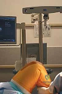
Operating room setup for navigated TKA requires specific ergonomic and spatial considerations. The optical camera array, which emits and detects infrared light reflected from the tracker spheres, must be positioned at the foot or side of the table, ensuring an uninterrupted line of sight to the surgical field. The primary surgeon, assistants, and scrub nurse must be acutely aware of this "cone of visibility." Any obstruction by a head, shoulder, or instrument will temporarily halt the system's tracking capabilities, causing frustrating delays. The navigation monitors should be positioned directly across from the primary surgeon, allowing for heads-up, continuous visual feedback without requiring awkward neck rotation.
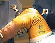
Patient positioning is standard for TKA but carries added critical nuances for navigation. The patient is placed supine. A specialized leg holder is utilized, but it is paramount that the hip is positioned in a neutral coronal and sagittal alignment. If the patient's pelvis is tilted or the hip is abducted during the dynamic registration of the hip center, the entire mechanical axis calculation can be subtly skewed. A pneumatic tourniquet is applied high on the thigh. During sterile draping, the surgeon must anticipate the location of the tracker pins (typically 10-15 cm proximal and distal to the joint line). Clear plastic drapes or specific cut-outs are often used to ensure the arrays remain sterile while maintaining perfect optical visibility for the camera.
Step-by-Step Surgical Approach and Fixation Technique
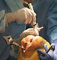
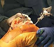
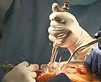
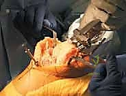
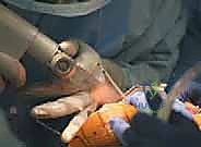
The surgical execution of a navigated TKA is a highly choreographed sequence. Following exsanguination and tourniquet inflation, a standard midline longitudinal skin incision is made, typically extending from the superior pole of the patella to the medial border of the tibial tubercle. Deep dissection proceeds to the extensor mechanism, where a medial parapatellar arthrotomy is performed. The patella is carefully everted or laterally subluxated, depending on tissue tension and surgeon preference. Meticulous hemostasis is achieved, and the fat pad is partially excised to allow unimpeded visualization of the lateral tibial plateau and the intercondylar notch.
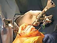
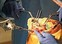
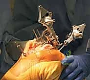
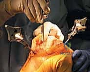
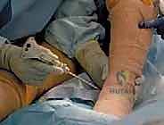
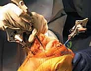
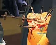
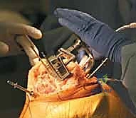
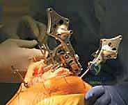
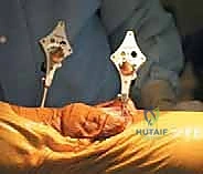
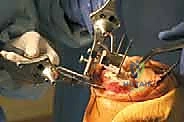
The defining initial step of navigated TKA is the placement of the reference arrays. Safe zones for pin placement are strictly adhered to. For the femur, two threaded 4mm or 5mm pins are placed percutaneously into the anteromedial diaphyseal/metaphyseal junction, approximately 10-15 cm proximal to the joint line. They must be placed bicortically for rigid stability but angled to avoid plunging into the posterior neurovascular structures. The tibial pins are similarly placed in the anteromedial tibia, distal to the planned resection level and medial to the tibial tubercle to avoid interfering with the cutting blocks or the extensor mechanism. Once the pins are secure, the sterile reflective arrays are attached and locked into position. Any micro-motion of these arrays during the case will invalidate the registration and require the process to be restarted.
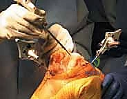
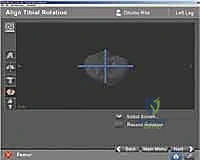
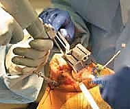
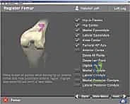
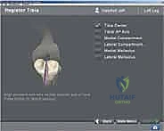
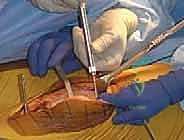
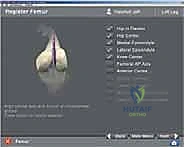
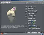
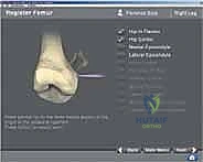
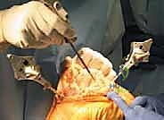
With the arrays visible to the camera, anatomical registration commences. The surgeon uses a calibrated, sterile optical probe to digitize the anatomy. First, the hip center is calculated kinematically by moving the femur through a series of rotational and circumduction maneuvers. The system's algorithm calculates the pivot point of this motion, establishing the proximal point of the femoral mechanical axis. Next, specific bony landmarks are probed: the distal and posterior femoral condyles, the medial and lateral epicondyles, the center of the tibial plateau, the tibial tubercle, and the medial and lateral malleoli. The accuracy of this step is paramount; probing osteophytes instead of true cortical bone will result in erroneous resection planes.
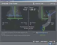
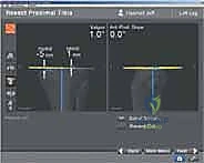
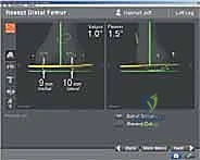
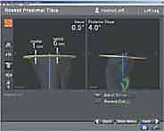
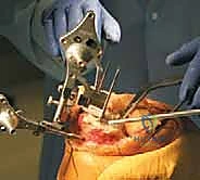
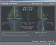
Once registration is complete, the system provides a real-time display of the limb's baseline alignment and soft-tissue laxity. The surgeon stresses the knee in varus and valgus at both 0 degrees (extension) and 90 degrees (flexion). This pre-resection gap analysis is the superpower of navigation. It allows the surgeon to visualize the exact millimeter dimensions of the medial and lateral compartments. Based on this data, the surgeon manipulates the virtual cutting planes on the monitor. The distal femoral cut is typically planned perpendicular to the mechanical axis, and the proximal tibial cut is planned with specific posterior slope (e.g., 3-5 degrees) and neutral coronal alignment.
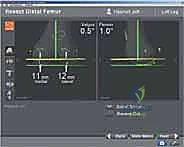
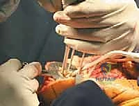
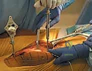
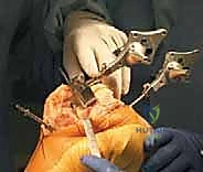
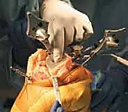
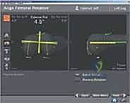
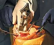
Guided by the navigation screen, the cutting blocks are pinned into place. The system verifies the exact resection depth, varus/valgus angle, and flexion/extension angle of the block before the saw is ever activated. After the distal femur and proximal tibia are resected, the extension gap is re-measured. The femoral component size and rotation are then finalized, often utilizing the measured flexion gap to ensure perfect symmetry with the extension gap. The 4-in-1 cutting block is navigated into position, setting the external rotation of the femur to optimize patellar tracking and balance the flexion space. Following the chamfer cuts, trial components are placed, and the knee is taken through a final, navigated dynamic range of motion to verify perfect kinematic restoration prior to definitive cementation.
Complications, Incidence Rates, and Salvage Management
While navigated TKA enhances precision, it introduces a unique set of technology-specific complications that the orthopedic surgeon must be prepared to manage. The most concerning of these are pin-site complications. The placement of 4mm to 5mm threaded pins into the diaphyseal or metaphyseal bone creates significant stress risers. In patients with poor bone quality, this can lead to iatrogenic cortical fractures either intraoperatively during pin insertion/removal or postoperatively during early rehabilitation. The incidence of pin-site fractures is reported in the literature to be between 0.1% and 0.5%.
Another critical complication is pin-site infection. The percutaneous nature of the trackers means that the pins traverse the skin barrier for the duration of the surgery. Thermal necrosis of the bone during drilling (if dull drills or insufficient irrigation are used) can create a nidus for infection. While superficial pin-site infections are generally manageable with oral antibiotics, deep tracking infections that communicate with the intramedullary canal or the joint space are catastrophic and require aggressive surgical debridement. Meticulous aseptic technique, sharp drill bits, and copious irrigation during pin placement are mandatory preventative measures.
Intraoperative technical failures also pose a significant risk. Tracker loosening or micro-motion after registration is a silent threat. If a tracker is bumped by a retractor or an assistant and shifts even a millimeter, the system's spatial map becomes entirely decoupled from the patient's actual anatomy. If the surgeon fails to recognize this and proceeds with the resections, severe malalignment will occur. Therefore, frequent verification checks—touching a known bony landmark with the probe to ensure the system accurately reads its location—must be integrated into the surgical workflow.
| Complication | Estimated Incidence | Prevention & Salvage Management |
|---|---|---|
| Pin-Site Fracture | 0.1% - 0.5% | Prevention: Avoid diaphyseal placement in osteoporotic bone; use unicortical pins if possible; avoid multiple drill passes. Salvage: Intraoperative plating; bypass with long-stem revision components; restricted weight-bearing post-op. |
| Tracker Loosening / Shift | 1.0% - 3.0% | Prevention: Bicortical pin purchase; strict "no-touch" zone around arrays; robust pin design. Salvage: Immediate re-registration of all anatomical landmarks; verification with manual alignment rods. |
| Pin-Site Infection | 0.5% - 1.0% | Prevention: Sharp drills to prevent thermal necrosis; copious irrigation; meticulous sterile draping. Salvage: Oral antibiotics for superficial; IV antibiotics and surgical debridement for deep/osteomyelitis. |
| System/Software Failure | < 1.0% | Prevention: Preoperative system checks; trained dedicated CAOS technician in the OR. Salvage: Abandon navigation; revert to conventional intramedullary/extramedullary instrumentation. |
| Registration Error (Malalignment) | 1.0% - 2.0% | Prevention: Meticulous debridement of osteophytes before mapping; precise identification of epicondyles and malleoli. Salvage: Intraoperative verification with drop rods; recutting bone if error is identified before cementation. |
If a catastrophic system failure occurs (e.g., camera malfunction, software crash) mid-procedure, the surgeon must be fully prepared to seamlessly transition to conventional instrumentation. Navigated TKA should never be performed by a surgeon who is not completely proficient in traditional, mechanical alignment techniques. The sterile field must always contain the standard intramedullary femoral guides and extramedullary tibial jigs as an absolute failsafe.
Phased Post-Operative Rehabilitation Protocols
The postoperative rehabilitation following a navigated TKA does not significantly differ from a conventional TKA in its phases, but the enhanced precision and optimized soft-tissue balancing often facilitate a more rapid and less painful recovery trajectory. Because navigation allows for precise gap balancing without the need for extensive, traumatic soft-tissue releases (such as aggressive medial collateral ligament pie-crusting), patients frequently exhibit less periarticular edema and reduced postoperative pain
Clinical & Radiographic Imaging Archive