Biomechanics of Implant Design and Fracture Fixation

Key Takeaway
Understanding the biomechanics of implant design and fracture fixation is paramount for orthopedic surgeons. Bone, an anisotropic material, exhibits distinct stress-strain behaviors under varying loads. This guide explores the structural properties of cortical and cancellous bone, mechanisms of fracture, and the load-deformation characteristics of implants. By mastering these principles, surgeons can optimize fixation constructs, prevent implant fatigue failure, and facilitate ideal environments for both direct and indirect bone regeneration.
Introduction to Orthopaedic Biomechanics
The foundation of operative orthopedics rests upon a profound understanding of biomechanics. The factors universally cited in evaluating the failure of bone—and the subsequent design of implants to stabilize it—include the type, magnitude, and rate of load, alongside the intrinsic material and structural properties of the bone itself.
Bone is a highly complex, viscoelastic, and anisotropic material. Anisotropy dictates that bone exhibits vastly different stress-strain relationships depending on the direction and vector of the applied stress. Furthermore, the structural behavior of bone varies significantly between its cortical and cancellous components, primarily due to differences in porosity, density, and the diameter of their respective cross-sections.
Clinical Pearl: In vitro biomechanical testing demonstrates that cortical bone is relatively brittle, fracturing when strain exceeds merely 2% of its original length. Conversely, cancellous bone is highly compliant and does not fail until strain exceeds 7%. This fundamental difference dictates why metaphyseal (cancellous) fractures often impact and compress, whereas diaphyseal (cortical) fractures shatter or splinter.
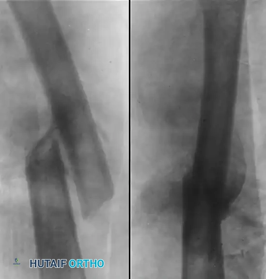
Mechanisms of Bone Failure and Fracture Patterns
In analyzing fracture patterns, the mode of loading offers critical insight into the mechanism of injury, the energy dissipated, the state of the soft tissue hinge, and the inherent stability of the resulting fracture. Loads applied to the musculoskeletal system are typically described as tension, compression, bending, shear, torsion, or a complex combination of these forces.
The specific mode of bone failure allows the astute orthopedic surgeon to predict the extent of the surrounding soft tissue injury, which is paramount for preoperative planning and selecting the appropriate surgical approach.
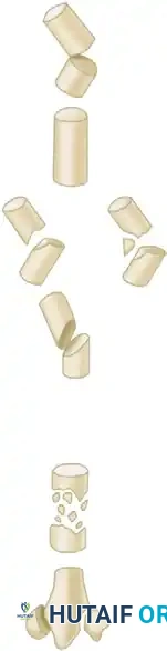
Summary of Long Bone Fracture Biomechanics
Below is a detailed breakdown of fracture patterns, their corresponding mechanisms of injury, and the expected state of the soft tissue hinge.
Transverse Fractures
Transverse fractures are primarily the result of pure bending forces. The failure initiates on the tension side of the bone and propagates transversely across the cortex.
* Mechanism: Bending
* Soft Tissue Hinge: Concavity
* Energy Level: Low
Spiral Fractures
Spiral fractures occur under pure torsion (rotational) loading. The fracture line spirals along the longitudinal axis of the bone, often creating a long, sharp fragment.
* Mechanism: Torsion
* Soft Tissue Hinge: Vertical segment
* Energy Level: Low
Oblique-Transverse (Butterfly) Fractures
When a bone is subjected to a combination of compression and bending, a butterfly fragment is often produced. The bending creates tension on one side (transverse component) and compression on the other, shearing off a triangular wedge.
* Mechanism: Compression + Bending
* Soft Tissue Hinge: Concavity or side of the butterfly fragment
* Energy Level: Moderate

Oblique Fractures
Short oblique fractures are typically generated by a combination of compression and bending forces, often with a shear component.
* Mechanism: Compression + Bending
* Soft Tissue Hinge: Concavity (though often destroyed depending on displacement)
* Energy Level: Moderate

Comminuted Fractures
Comminution implies a high-energy transfer to the bone, resulting in multiple fragments. The loading mode is often a complex, variable combination of torsion, bending, and axial loading.
* Mechanism: Torsion / Variable complex loads
* Soft Tissue Hinge: Destroyed
* Energy Level: High

Metaphyseal Compression Fractures
Occurring in the cancellous bone of the metaphysis (e.g., tibial plateau, distal radius), these fractures are driven by pure axial compression, leading to trabecular impaction.
* Mechanism: Compression
* Soft Tissue Hinge: Variable
* Energy Level: Variable
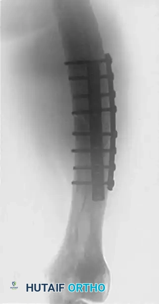
Biomechanics of Implant Design
Devices used to stabilize the skeleton—whether intramedullary nails, plates, screws, or external fixators—are subjected to continuous loading and deforming forces. Unlike the native bone during the initial trauma, these implants rarely fail due to acute load-to-failure. Instead, implant failure is almost exclusively due to fatigue if the bone does not regenerate rapidly enough to share and eventually assume the physiological load.
Material vs. Structural Properties
To understand implant behavior, one must differentiate between material and structural properties:
1. Material Properties: Expressed by stress-strain curves. These properties are intrinsic to the metal alloy itself (e.g., Titanium alloy Ti-6Al-4V vs. 316L Stainless Steel), independent of the implant's shape.
2. Structural Properties: Expressed by load-deformation (or load-deflection) curves. These properties depend on both the material and the geometric design of the implant (e.g., a 10mm solid nail vs. a 10mm cannulated nail).
The Load-Deflection Curve
The structural integrity of an implant is defined by its load-deflection curve, which features several critical phases:
* Elastic Phase: The working area of the implant. Deformation is temporary; the implant returns to its original shape once the load is removed. Most implants, particularly intramedullary nails, are designed to function strictly within this phase.
* Proportional Limit / Yield Point: The exact point where elastic deformation transitions into plastic deformation.
* Plastic Phase: Deformation becomes permanent. The implant bends and will not return to its original shape.
* Ultimate Load: The maximum load the implant can sustain before structural failure begins.
* Load to Failure: The point at which the implant breaks.
* Stiffness: Represented by the slope of the elastic phase. A steeper slope indicates a stiffer implant.
Surgical Warning: If an implant is repeatedly loaded into its plastic phase, or if it sustains millions of cycles in its elastic phase without the support of healed bone, fatigue failure (breakage) is inevitable. The race in fracture fixation is always between bone healing and implant fatigue.
Moments of Inertia
The structural properties of an implant are heavily modified by its cross-sectional geometry to obtain the desired stiffness and strength:
* Area Moment of Inertia: Dictates resistance to bending. For a solid cylinder (like a pin), it is proportional to the radius to the fourth power ($r^4$). Therefore, a small increase in the diameter of a pin or nail exponentially increases its bending stiffness.
* Polar Moment of Inertia: Dictates resistance to torsion.
Theoretically, there is an optimal elastic range of deformation for implants that favors bone regeneration. However, this range differs drastically depending on whether the surgeon is aiming for direct (primary) bone healing (requiring absolute stability and minimal strain) or indirect (secondary) bone healing (requiring relative stability and controlled micromotion to stimulate callus formation).
Wire and Pin Fixation: Kirschner Wires and Steinmann Pins
Kirschner wires (K-wires) and Steinmann pins are ubiquitous in orthopedic surgery, frequently utilized for both provisional (temporary) and definitive fracture fixation. They resist shear, translation, and rotation when used in specific configurations, but their biomechanical limitations must be strictly respected.
Biomechanical Limitations of Wires
Because their cross-sectional diameter is small, their area moment of inertia is low. Consequently, their resistance to bending loads is exceptionally poor.
* If used as a standalone definitive fixation device, they must be supplemented by external support, such as bracing or casting, to neutralize bending forces.
* Rarely does wire fixation alone provide sufficient stability to allow for early functional rehabilitation and active range of motion of the extremity.
Indications for Pin and Wire Fixation
Pin or wire fixation is highly effective for small fragments in metaphyseal and epiphyseal regions where compressive forces can be utilized and bending forces are minimal. Common indications include:
* Distal radius (Colles) fractures.
* Displaced metacarpal and phalangeal fractures (after closed or limited open reduction).
* Fractures of the distal foot (e.g., metatarsal, Lisfranc provisional fixation).
* Tension band constructs (combined with cerclage wire) for the patella, olecranon, and proximal humerus.
* Provisional fixation of complex articular fractures prior to definitive plating.
Surgical Technique: Insertion Principles
When used as definitive fixation, K-wires are usually inserted percutaneously or via a limited open approach. This minimally invasive technique protects the soft tissue envelope and preserves the periosteal blood supply, theoretically permitting maximal bone regeneration.
Step-by-Step Insertion Protocol
- Positioning and Imaging: The patient is positioned to allow unimpeded access for the image intensifier (fluoroscopy). Most pin insertions are performed under dynamic fluoroscopic control to ensure perfect trajectory and depth.
- Reduction: The fracture must be anatomically reduced and held securely (manually or with reduction forceps) prior to pin insertion.
- Trajectory Planning: Plan the pin trajectory to cross the fracture site at an optimal angle (often perpendicular to the fracture line or in a crossed configuration for rotational stability).
- Insertion:
- Use a wire driver or power drill.
- CRITICAL: Insert the wire slowly and with frequent stops.
- Continuous, high-speed drilling generates excessive friction, leading to thermal osteonecrosis. Dead bone around the pin tract leads to premature pin loosening and increases the risk of pin tract infection.
- Soft Tissue Protection: Ensure that tendons, neurovascular bundles, and skin are not tethered or wound around the pin during insertion. Use a soft tissue protector or drill guide when operating near critical structures.
Pitfall - The "Windlass" Effect: When inserting a K-wire percutaneously, especially in the hand or wrist, the spinning wire can catch a tendon or nerve, winding it around the shaft and causing devastating iatrogenic injury. Always incise the skin with a scalpel and spread the soft tissues down to the bone with a hemostat before applying power to the wire.
Smooth vs. Threaded Wires
Surgeons must choose between smooth and threaded wires based on the clinical scenario:
* Smooth Wires: Preferred for definitive fixation where the pins will be removed in the clinic after fracture healing. They are easier to extract and cause less pain upon removal. However, they offer no resistance to axial pull-out.
* Threaded Wires: Provide superior grip and hold fractures in place better, making them ideal for temporary fixation or situations where pin migration is a high risk.
* Warning: When using threaded wires, the fracture fragments must be held tightly together during insertion. A threaded wire will not compress a fracture; if a gap exists, the threads will hold the fracture in distraction, leading to nonunion.
* Threaded wires also carry a higher risk of breakage at the thread-smooth junction if the cortical bone is exceptionally hard.
Implant Fatigue and Notching
When manipulating wires (e.g., bending the ends outside the skin to prevent migration), the surgeon must avoid notching the wire with pliers or wire benders. A notch acts as a stress riser, drastically reducing the area moment of inertia at that specific point. This exponentially shortens the fatigue life of the implant, making it highly susceptible to breakage under cyclical loading before the fracture has healed.
Postoperative Protocols and Rehabilitation
The preoperative plan must meticulously consider the forces that the internal or external fixation will sustain. The chosen implant's fatigue life directly dictates the postoperative rehabilitation program.
- Absolute Stability Constructs (e.g., Lag screws, Compression plates): Designed for direct bone healing. These constructs cannot tolerate cyclical loading. Rehabilitation must focus on early range of motion to prevent stiffness, but strictly limit weight-bearing until radiographic evidence of obliteration of the fracture line is observed.
- Relative Stability Constructs (e.g., Intramedullary nails, Bridge plates, K-wires with casts): Designed for indirect bone healing via callus formation. These constructs tolerate—and in fact, require—controlled micromotion. Rehabilitation often allows for earlier, progressive weight-bearing, as the cyclical axial loading stimulates robust callus formation, provided the implant's elastic limit is not exceeded.
By integrating the principles of bone anisotropy, fracture mechanics, and implant structural properties, the orthopedic surgeon can construct a biomechanically optimized environment that ensures implant survival and rapid, reliable fracture union.
You Might Also Like