The Biomechanics of Motion: Understanding Degrees of Flexion
02 إبريل 2026
35 min read
114 Views

Key Takeaway
In this comprehensive guide, we discuss everything you need to know about The Biomechanics of Motion: Understanding Degrees of Flexion. Biomechanics examines forces on the living body, encompassing kinematics, the study of motion without forces, and kinetics, relating forces to motion. Key principles involve analyzing vector quantities like force and velocity, often broken into components. This field is essential for understanding movements like angular displacement, measured in specific degrees of flexion, to assess joint mechanics and apply Newton's laws for dynamic analysis.
-
Basic concepts
- Definitions
- Biomechanics—science of forces, internal or external, on the living body
- Statics—action of forces on rigid bodies in a system in equilibrium
- Dynamics—bodies that are accelerating and the related forces
- Kinematics—study of motion (displacement, velocity, and acceleration) without reference to forces
- Kinetics—relates the effects of forces to motion
- Principal quantities
- Basic quantities—described by International System of Units (SI); metric system
- Length (m), mass (kg), time (sec)
- Derived quantities: derived from basic quantities
- Velocity
- Time rate of change of displacement (meters/second)
-
Rate of translational displacement:
linear velocity -
Rate of rotational displacement:
angular velocity - Acceleration
- Force
- Time rate of change of velocity (m/sec2)
-
Can also be linear or angular
□ Newton’s laws - Action causing acceleration of a mass (body) in a certain direction
- Unit of measure: newton (N) = kg • m/sec2
- First law: inertia
- If the net external force ( F ) acting on a body is zero, the body remains at rest or moves with a constant velocity.
- This law allows static analysis: Σ F = 0 (sum of external forces = zero)
- Second law: acceleration
-
Acceleration
(a)
of an object of mass
(m)
is directly proportional to the force
(F)
applied to the object:

- This law is used in dynamic analysis.
- Third law: reactions
- For every action (force), there is an equal and opposite reaction (force).
- This law leads to free-body analysis.
- This law also assists in the study of interacting bodies.
- Scalar and vector quantities
- Scalar quantities
- Have magnitude but no direction
- Examples: volume, time, mass, and speed (not velocity)
- Vector quantities
- Have magnitude and direction
- Examples: force and velocity
- Vectors have four characteristics
- Magnitude (length of the vector)
- Direction (head of the vector)
- Point of application (tail of the vector)
- Line of action (orientation of the vector)
- Vectors can be added, subtracted, and split into components (resolved)
-
Resultant of two vectors: principle of
“parallelogram of forces” - Free-body analysis
- Forces, moments, and free-body diagrams to analyze the action of forces on bodies
- Force
-
A mechanical push or pull (load) that causes
external (acceleration) and internal (strain) effects - Unit of measure: the newton (N)
- Force vectors ( F ): can be split into independent components for analysis
-
Usually in the
x
and
y
directions (
F
x
,
F y ). - With angle (θ) between F x and F y .
- A normal force is perpendicular to the surface on which it acts.
- A tangential force is parallel to the surface.
- A compressive force shrinks a body in the direction of the force.
- A tensile force elongates a body.
- Moment ( M )
- Rotational effect of a force
-
Moment = force (
F
) multiplied by the perpendicular distance (the moment arm or lever arm =
d
) from point of rotation:

- Torque is a moment from a force perpendicular to the long axis of a body, causing rotation.
- A bending moment is from a force parallel to the long axis.
- The mass moment of inertia is the resistance to rotation.
-
Product of mass times the square of the moment arm:

- Affects angular acceleration
- Free-body diagram
- A free-body diagram is a sketch of a body (or segments) isolated from other bodies that shows all forces acting on it.
- The weight of each object acts through its center of gravity.
- Center of gravity in the human body is just anterior to S2.
- Finite element analysis
- Complex geometric forms and material properties are modeled.
- A structure is modeled as a finite number of simple geometric forms.
- Typically triangular or trapezoidal elements
- A computer matches forces and moments between neighboring elements.
- Finite element analysis is often used to estimate internal stresses and strains.
- Example: stress/strain at bone-implant interface
- Other important basic concepts
- Work
- The product of a force and the displacement it causes
- Work ( W ) = force ( F; vector components parallel to displacement) × distance (displacement produced by F )
- Unit of measure: joule (J) = N • m
- Energy
-
Ability to perform work (unit of
measure is also joule) - Laws of conservation of energy:
- Energy is neither created nor destroyed.
- It is transferred from one state to another.
- Potential energy
- Stored energy
- Potential of a body to do work as a result of its position or configuration (e.g., strain energy)
-
Kinetic energy—energy caused by
motion (½mv2) - Friction (f)
- Resistance to motion when one body slides over another
- Produced at points of contact
- Oriented opposite to the applied force
- When applied force exceeds f , motion begins.
- Proportional to coefficient of friction and applied normal (perpendicular) load
- Piezoelectricity
- Independent of contact area and surface shape
-
Biomaterials
□ Strength of materials - Electrical charge when a force deforms a crystalline structure (e.g., bone)
- Concave (compression) side: charge is electronegative
- Convex (tension) side: charge is electropositive
- Study of relations between externally applied loads and resulting internal effects
- Loads
- Forces acting on a body
- Compression, tension, shear, and torsion
- Deformations
- Temporary (elastic) or permanent (plastic) change in shape
- Load changes produce deformational changes.
- Elasticity—ability to return to resting length after undergoing lengthening or shortening
- Extensibility—ability to be lengthened
- Stress
- Intensity of internal force
- Stress = force/area
- Internal resistance of a body to a load
- Unit of measure: pascal (Pa) = N/m2
- Strain
- Normal stresses
- Compressive or tensile
- Perpendicular to the surfaces on which they act
- Shear stresses
- Parallel to the surfaces on which they act
- Cause a part of a body to be displaced in relation to another part
- Stress differs from pressure:
-
Pressure is the distribution of an
external force to a solid body. - However, they share the same definition (force/area) and unit of measure (Pa).
- Relative measure of deformation (six components) resulting from loading
- Strain = change in length/original length
- Can also be normal or shear
- Strain is a proportion; it has no units.
- Strain rate
-
Strain divided by time load is applied
(units = sec −1). - Hooke’s law: stress is proportional to strain up to a limit.
- The proportional limit
- Within the elastic zone
- Young’s modulus of elasticity (E)
- Measure of material stiffness
- Also a measure of the material’s ability to resist deformation in tension
- E = stress/strain
-
E is the slope in the elastic range of the stress-strain curve.

FIG. 1.60 Stress-strain curve. E, Young’s modulus of elasticity. - The critical factor in load-sharing capacity
- Linearly perfect elastic material
- A straight stress-strain curve to the point of failure
- Modulus = stress at failure (ultimate stress) divided by strain at failure (ultimate strain)
- E is unique for every type of material
- A material with a higher E can withstand greater forces than can material with a lower E.
- Shear modulus
- Ratio of shear stress to shear strain
- A measure of stiffness
- Unit of measure: pascal (Pa)
- Stress-strain curve ( Fig. 1.60)
- Derived by loading a body and plotting stress versus strain
- The curve’s shape varies by material.
- Proportional limit—transition point at which stress and strain are no longer proportional
- The material returns to its original length when stress is removed: elastic behavior.
- Elastic limit (yield point)
- This is the transition point from elastic to plastic behavior.
- Beyond this point, the material’s structure is irreversibly changed.
- The elastic limit equals 0.2% strain in most metals.
- Plastic deformation—irreversible change after load is removed
- Occurs in the plastic range of the curve
- After the elastic limit, before the breaking point
- Ultimate strength—maximum strength obtained by the material
- Breaking point—point at which the material fractures
- Ductile—if deformation between elastic limit and breaking point is large
- Brittle—if deformation between elastic limit and breaking point is small
- Strain energy (toughness)
- Capacity of material (e.g., bone) to absorb energy
- Area under the stress-strain curve
- Total strain energy = recoverable strain energy (resilience) + dissipated strain energy
- A measure of the toughness of material
- Material definitions
- Brittle materials (e.g., PMMA)
- Ability to absorb energy before failure
- Stress-strain curve is linear up to failure.
- These materials undergo only recoverable (elastic) deformation before failure.
- They have little or no capacity for plastic deformation.
- Ductile materials (e.g., metal)
- These materials undergo large plastic deformation before failure.
- Ductility is a measure of post-yield deformation.
- Viscoelastic materials (e.g., bone and ligaments)
- Stress-strain behavior is time-rate dependent.
- Depends on load magnitude and rate at which the load is applied
- A function of internal friction
- Exhibit both fluid (viscosity) and solid (elasticity) properties
- Modulus increases as strain rate increases.
- Exhibit hysteresis
- Loading and unloading curves differ.
- Energy is dissipated during loading.
- Most biologic tissues exhibit viscoelasticity.
- Isotropic materials
- Mechanical properties are the same for all directions of applied load (e.g., as with a golf ball).
- Anisotropic materials
- Mechanical properties vary with the direction of the applied load.
- Example: bone is stronger with axial load than with radial load.
- Homogeneous materials
- Have a uniform structure or composition throughout
- Rigidity
- Bending rigidity of a rectangular structure:
-
Proportional to the base multiplied by the height cubed:

□ Metals - Bending rigidity of a cylinder
- Related to the fourth power of the radius
- Examples: intramedullary nails, half-pins
- Fatigue failure
- Occurs with cyclic loading at stress below ultimate tensile strength
- Depends on magnitude of stress ( S ) and number of cycles ( n )
- Endurance limit
- Maximum stress under which the material will not fail regardless of number of loading cycles
-
If the stress is below this limit, the material may be loaded cyclically an
infinite number of times (>106 cycles) without breaking. - Above this limit, fatigue life is expressed by the S-n curve:
- Creep (cold flow)
- Progressive deformation response to constant force over an extended period
- Sudden stress followed by constant loading causes continued deformation.
- Can produce permanent deformity
- May affect mechanical function (e.g., in TJA)
- Corrosion ( Table 1.43)
- Chemical dissolving of metals
-
Table 1.43 Types of Corrosion Corrosion Description --- Galvanic |
Dissimilar metals
a ; electrochemical destruction Crevice | Occurs in fatigue cracks with low O2 tension Stress | Occurs in areas with high stress gradients Fretting | From small movements abrading outside layer Other | For example, inclusion, intergranular
a Metals such as 316 L stainless steel and cobalt-chromium-molybdenum (Co-Cr-Mo) alloy produce galvanic corrosion. - May occur in the body’s high-saline environment
- Stainless steel (type 316L)
- The metal most susceptible to both crevice corrosion and galvanic corrosion
- Risk of galvanic corrosion highest between 316L stainless steel and cobalt-chromium (Co-Cr) alloy
- Modular components of THA
- Direct contact between similar or dissimilar metals at the modular junctions
- Results in corrosion products
- Examples: metal oxides, metal chlorides
- Corrosion can be decreased in the following ways:
- Using similar metals
- Proper implant design
- Passivation by an adherent oxide layer
- Effectively separates metal from solution
- Example: stainless steel coated with chromium oxide
- Types of metals
- Orthopaedic implants
- Three types of alloys: steel (iron-based), cobalt-based, titanium-based
- 316L stainless steel
- Iron-carbon, chromium, nickel, molybdenum, manganese
- Nickel: increases corrosion resistance and stabilizes molecular structure
- Chromium: forms a passive surface oxide, improving corrosion resistance
- Molybdenum: prevents pitting and crevice corrosion
- Manganese: improves crystalline stability
-
“L”—low in carbon: greater corrosion
resistance - Cobalt alloys
- Cobalt-chromium-molybdenum (Co-Cr-Mo)
-
65% cobalt, 35%
chromium, 5% molybdenum - Special forging process
- Nickel may be added to improve ease of forging.
- Greater ultimate strength than titanium
- Ion release
- Co-Cr: macrophage proliferation and synovial degeneration
- Ions excreted through the kidneys
- Titanium alloy (Ti-6Al-4V)
- Poor resistance to wear (notch sensitivity)
- Particulate may incite a histiocytic response.
-
The relationship between titanium and neoplasms is uncertain.

--- FIG. 1.61 Comparison of Young’s modulus (relative values, not to scale) for various orthopaedic materials. Al2O3, Alumina; Co-Cr-Mo, cobalt-chromium-molybdenum; PMMA, polymethylmethacrylate. - Nonmetal materials
- Polishing, passivation, and ion implantation improve its fatigue properties.
- Titanium is extremely biocompatible
- Rapidly forms an adherent oxide coating (self-passivation); decreases corrosion
- Most closely emulates axial and torsional stiffnesses of bone
- High yield strength
- Tantalum—passive material designed to elicit a response (bone ingrowth)
- Surface oxide layer as barrier to corrosion
- Used as augmentation of cancellous defects
- Stiffness (E) differences ( Fig. 1.61)
- Polyethylene (discussed in Chapter 5, Adult R reconstruction)
- PMMA (bone cement)
- Used for fixation and load distribution for implants
- Acts as a grout, not an adhesive
- Mechanically interlocks with bone
-
Reaches ultimate strength within 24 hours
- Can be used as an internal splint for the patient with poor bone stock
- PMMA can be used as a temporary internal splint until the bone heals.
- If bone fails to heal, PMMA will ultimately fail.
- Poor tensile and shear strength
- Is strongest in compression and has a low E
- Not as strong as bone in compression
- Reducing voids (porosity) increases cement strength and decreases cracking.
- Vacuum mixing, centrifugation, good technique
- Cement failure often caused by microfracture and fragmentation.
- Insertion can lead to a precipitous drop in BP.
- Wear particles can incite a macrophage response
- Leads to prosthesis loosening
- Ceramics
- Silicones
- Polymers for replacement in non–weight-bearing joints
- Poor strength and wear capabilities
- Frequent synovitis with extended use
- Metallic and nonmetallic elements bonded ionically in a highly oxidized state
- Good insulators (poor conductors)
- Biostable (inert) crystalline materials such as Al2O3 (alumina) and ZrO2 (zirconium dioxide)
- Bioactive (degradable) noncrystalline substances such as bioglass
- Typically brittle (no elastic deformation)
- High modulus (E)
- High compressive strength
- Low tensile strength
- Low yield strain
- Poor crack resistance characteristics
- Low resistance to fracture
- Best wear characteristics, with polyethylene and a low oxidation rate
- High surface wettability and high surface tension
- Highly conducive to tissue bonding
- Less friction and diminished wear (“smooth surface”)
- Small grain size allows an ultrasmooth finish.
- Less friction
- Calcium phosphates (e.g., hydroxyapatite) may be useful as coatings (plasma sprayed) to increase attachment strength and promote bone healing.
- Mechanical properties of tissue
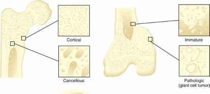
- Bone
- Composite of collagen and hydroxyapatite
- Collagen: low E , good tensile strength, poor compressive strength
- Calcium apatite: stiff, brittle, good compressive strength
- Anisotropic
- Strongest in compression
- Weakest in shear
- Intermediate in tension
- Resists rapidly applied loads better than slowly applied loads
- Cancellous bone is 25% as dense, 10% as stiff, and 500% as ductile as cortical bone.
- Cortical bone excellent at resisting torque.
- Cancellous bone good at resisting compression and shear.
- Bone is dynamic.
- Able to self-repair
- Changes with aging: stiffer and less ductile
- Changes with immobilization: weaker
- Bone aging
- To offset loss in material properties, bone remodels to increase inner and outer cortical diameters.
- Area moment of inertia increases.
- Bending stresses decrease.
- Stress concentration effects
- Occur at defect points within bone or at implant-bone interface (stress risers)
- Reduce overall loading strength
- Stress shielding by load-sharing implants
- Induces osteoporosis in adjacent bone
- Decreases normal physiologic bone stresses
- Common under plates and at the femoral calcar in high-riding THA
- A hole measuring 20%–30% of bone diameter reduces strength up to 50%.
- Regardless of whether it is filled with a screw
- Area returns to normal 9–12 months after screw removal.
- Cortical defects can reduce strength 70% or more.
- Oval defects less than rectangular defects
- Fracture
- Smaller stress riser (concentration)
- Type is based on mechanism of injury.
- Tension: typically transverse and perpendicular to load and bone axis
- Compression: crush fracture
- Shear
- Commonly around joints
- Load parallel to the bone surface
- Ligaments and tendons
- Fracture parallel to the load
- Bending
- Eccentric loading or direct blows
- Begins on the tension side of the bone
- Continues transversely/oblique
- May bifurcate to produce a butterfly fragment
- High-velocity bending: produces comminuted butterfly fracture
- Four-point bending: produces segmental fracture
- Torsion
- Shear and tensile stresses around the longitudinal axis
- Most likely to result in a spiral fracture
- Torsional stresses proportional to the distance from the neutral axis to the periphery of a cylinder
- Greatest stresses in a long bone under torsion are on the outer (periosteal) surface
- Comminution
- A function of the amount of energy transmitted to bone
- Can sustain 5%–10% tensile strain before failure.
- In contrast, bone can sustain only 1%–4% tensile strain.
- Failure commonly results from tension rupture of fibers and shear failure among fibers.
- Most ligaments can undergo plastic strain to the point that function is lost but structure remains in continuity.
- Articular cartilage
- Ultimate tensile strength is only 5% that of bone.
- E is only 0.1% that of bone.
- However, because of its viscoelastic properties, is well suited for compressive loading.
- Metal implants
- Screws
- Plates
- Is biphasic
- Solid phase depends on structural matrix.
- Fluid phase depends on deformation and shift of water within solid matrix.
- Relatively soft and impermeable solid matrix requires high hydrodynamic pressure to maintain fluid flow.
- Significant support provided by the fluid component
- Stress-shielding effect on the matrix
- Pitch: distance between threads
- Lead: distance advanced in one revolution
- Root diameter: minimal/inner diameter is proportional to tensile strength
- Outer diameter: determines holding power (pullout strength)
- To maximize pullout strength
- Large outer diameter
- Small root diameter
- Fine pitch
- Strength varies with material and moment of inertia.
-
Bending stiffness is proportional to the third
- power of the thickness (t 3 ).
-
Doubling thickness increases
bending stiffness eightfold. - Plates are load-bearing devices.
- Most effective on a fracture’s tension side
- Types include:
- Static compression
- Best in upper extremity
- Can be stressed for compression
- Dynamic compression
- Example: tension band plate
- Neutralization
- Resists torsion
- Buttress
- Blade
- Locking
- Protects bone graft
- Stress concentration at open screw holes can lead to implant failure.
- Increased resistance to torsional deformation
- Absorb axial forces transmitted from screws
- Do not require compression to bone; preserve periosteal blood supply
- Biomechanical advantages for osteoporotic fractures without cortical contact
- Hybrid locking
- Both nonlocked and locked screws are used.
- Nonlocked screws assist in reduction.
- Locked screws create a fixed-angle device or can be used in patients with osteoporosis.
- Intramedullary nails
- Load-sharing devices
-
Bicortical locked screws provide increased strength in torsion compared with unicortical locked screws.
- Require high polar moment of inertia to maximize torsional rigidity and strength
- Mechanical characteristics
- Torsional rigidity
- Amount of torque needed to produce a unit angle of torsional deformation
- Depends on both material properties (shear modulus) and structural properties (polar moment of inertia)
- Bending rigidity
- Amount of force required to produce a unit amount of deflection
- Depends on both material properties (elastic modulus) and structural properties (area moment of inertia, length)
-
Related to the fourth power of the nail’s radius
- Increasing nail diameter by 10% increases bending rigidity by 50%.
- Better at resisting bending forces than rotational
-
Reaming
forces - Allows greater torsional resistance
- Larger contact area
- A larger nail; increased rigidity and strength
- Unslotted nails
- Smaller diameter
- Stronger fixation
- At the expense of flexibility
- Increased torsional stiffness: greatest advantage of closed-section nails over slotted nails
- Intramedullary nail insertion for femoral shaft fracture
- External fixators
- Hoop stresses are lowest for a slotted titanium alloy nail with a thin wall
- Posterior starting points decrease hoop stresses and iatrogenic comminution of fractures
- Implant failure is more common with smaller-diameter unreamed nails
- Conventional external fixators
- Fracture reduction is the most important factor for stability of fixation with external fixation.
- Other factors to enhance stability (rigidity) include
- Larger-diameter pins (second most important factor)
- Additional pins
- Decreased bone-rod distance
- Pins in different planes
- Pins separated by more than 45 degrees
- Increased mass of the rods or stacked rods
- A second rod in the same plane increases resistance to bending.
- Rods in different planes
- Increased spacing between pins
- Placement of central pins closer to the fracture site
- Placement of peripheral pins farther from the fracture site (near-near, far-far).
- Circular (Ilizarov) external fixators
- Thin wires (usually 1.8 mm in diameter)
- Fixed under tension (usually between 90 and 130 kg)
- Circular rings
- Half-pins may also be used.
- Offer better purchase in diaphyseal (not metaphyseal) bone
- Optimum orientation of implants on the ring
- At a 90-degree angle to each other
- Maximizes stability
- A 90-degree angle not always possible
- Anatomic constraints such as neurovascular structures
- Bending stiffness of frame
- Independent of the loading direction
- Because the frame is circular
- Each ring should have at least two implants.
- Wires or half-pins may be used.
- The construct is most stable when an olive wire and a half-pin are at a 90-degree angle to each other on a ring.
- Two wires are used on a ring.
- One wire should be superior to the ring and one inferior.
- Tensioned wires on the same side can cause the ring to deform.
- Factors that enhance stability of circular external fixators
- Larger-diameter wires (and half-pins)
- Decreased ring diameter
- Use of olive wires
-
Additional wires or half-pins (or
both) - Wires (or half-pins or both) crossing at a 90-degree angle
- Increased wire tension (up to 130 kg)
- Placement of the two central rings close to the fracture site
- Decreased spacing between adjacent rings
- Increased number of rings
- Joint arthroplasty implants: discussed in Chapter 5, Adult Reconstruction chapter
-
Biomechanics
- General definitions
- Degrees of freedom
-
Rotations and translations each occur in the
x, y,
and z planes. - Thus six parameters, or degrees of freedom, describe motion.
- Translations may be relatively insignificant for many joints.
- Are often ignored in biomechanical analyses
- Joint reaction force (R)
- R is the force within a joint in response to forces acting on the joint.
- Both intrinsic and extrinsic
- Muscle contraction about a joint: the major contributing factor
- R is correlated with predisposition to degenerative changes.
- Joint contact pressure (stress) can be minimized by
- Decreasing R
- Increasing contact area
- Coupled forces—rotation about one axis causes obligatory rotation about another axis (occurs in some joints).
-
Such movements (and associated forces) are
coupled. - Example: lateral bending of the spine accompanied by axial rotation
- Joint congruence
- Related to the fit of two articular surfaces
-
A necessary condition for joint
motion - Can be evaluated radiographically
- High congruence increases joint contact area
- Low congruence decreases joint contact area
- Movement out of a position of congruence increases stress in cartilage.
- Allows less contact area for distribution of joint reaction force
- Predisposes the joint to degeneration
- Instant center of rotation
- Point about which a joint rotates
- In some joints (knee), the instant center changes during the arc of motion, following a curved path.
- Effect of joint translation and morphologic features
- It normally lies on a line perpendicular to the tangent of the joint surface at all points of contact.
- Rolling and sliding ( Fig. 1.62)
- During motion, almost all joints roll and slide to remain in congruence.
- Pure rolling:
- Instant center of rotation is at the rolling surfaces.
- Contacting points have zero relative velocity.
-
No “slipping” of one surface on the other

--- FIG. 1.62 (A) Rolling contact occurs when the circumferential distance of the rolling object equals the distance traced along the plane. This can occur only when there is no sliding—that is, when the relative velocity at the point of contact (P) is zero. (B) For rolling contact, the point P of the wheel has zero velocity because it is in contact with the ground. Therefore P is the instant center of rotation (ICR) of the wheel. This diagram shows the actual velocity of points along the wheel as it rolls along the ground. (C) Rolling and sliding contact occurs when the relative velocity at the contact point is not zero.
(D) Pure sliding occurs when the wheel rotates about a stationary axis (O) . In this case, the wheel would have no forward motion.
From Buckwalter JAet al: Orthopaedic basic science: biology and biomechanics of the musculoskeletal system, ed 2, Rosemont, IL, 2000, American Academy of Orthopaedic Surgeons, p 145. - Pure sliding
- Occurs with pure translation or rotation about a stationary axis
- No angular change in position
- No instant center of rotation
- “Slipping” of one surface on the other
- Friction and lubrication
- Friction : resistance between two objects as one slides over the other
- Not a function of contact area
- Coefficient of friction: 0 = no friction
- Lubrication: decreases resistance between surfaces
- Hip biomechanics
- Articular surfaces, lubricated with synovial fluid, have a coefficient of friction 10 times better than that of the best synthetic systems.
- Coefficient of friction for human joints: 0.002–0.04
- Coefficient of friction for metal-on-UHMWPE (ultra-high-molecular-weight polyethylene) joint arthroplasty: 0.05–0.15
- Not as good as that of human joints
-
Elastohydrodynamic lubrication
-
Primary lubrication mechanism for articular cartilage during dynamic function
- Kinematics
- ROM ( Table 1.44)
- Instant center
- Simultaneous triplanar motion for this ball-and-socket joint makes analysis impossible.
- Kinetics
- Joint reaction force (R) in the hip can reach three to six times body weight (W).
- Primarily as a result of contraction of the muscles crossing the hip
- Decreases with cane in contralateral hand
- Other considerations
- Stability
- Sourcil
- Deep-seated ball-and-socket joint is intrinsically stable.
- Condensation of subchondral bone under superomedial acetabulum
- R is maximal at this point
- Gothic arch
- Remodeled bone supporting the acetabular roof
- Sourcil at its base
- Neck-shaft angle
- Varus angulation
- Decreases R
- Increases shear across the neck
- Leads to shortening of the lower extremity
- Alters muscle tension resting length of the abductors
- May cause a persistent limp
- Valgus angulation
- Increases R
- Decreases shear
- Neutral or valgus angulation better for THA
- PMMA resists shear poorly
- Arthrodesis ( Fig. 1.63)
- Position: 25–30 degrees of flexion, 0 degrees of abduction and rotation
- External rotation is better than internal rotation.
- If the implant is fused in abduction, the patient will lurch over the affected lower extremity with an excessive trunk shift.
- This will later result in low back pain.
- Knee biomechanics
- Kinematics
- Effects
- Increases oxygen consumption
- Decreases gait efficiency to approximately 50% of normal
- Increases transpelvic rotation of the contralateral hip
- ROM
- 10 degrees of extension (recurvatum) to 130 degrees of flexion
- Functional ROM is nearly full extension to about 90 degrees of flexion.
- 117 degrees: required for squatting and lifting
- 110 degrees: required for rising from a chair after TKA
- Rotation varies with flexion
- At full extension, rotation is minimal.
- At 90 degrees of flexion, ROM is 45 degrees of external rotation and 30 degrees of internal rotation.
- Amount of abduction or adduction is essentially 0 degrees.
- A few degrees of passive motion are possible at 30 degrees of flexion.
-
Table 1.44 Hip Biomechanics: Range of Motion Average Functional Motion Range Range (Degrees) (Degrees) --- Flexion | 115
| 90 (120 to
squat) Extension | 30
| Abduction | 50
| 20 Adduction | 30
| Internal rotation | 45
| 0 External rotation | 45
| 20 -
Knee motion is complex about a
changing instant center of rotation. - Polycentric rotation
- Excursions of 0.5 cm for the medial meniscus and 1.1 cm for the lateral meniscus are possible during a 120-degree arc of motion.
- Kinetics
- Joint motion
- Instant center traces a J-shaped curve about the femoral condyle.
- Moves posteriorly with flexion
- Flexion and extension involve both rolling and sliding.
- Femur rotates internally (tibia rotates externally) during the last 15 degrees of extension
- “Screw home” mechanism
- Related to differences in radii of curvature for the medial and lateral femoral condyles and the musculature
- Posterior rollback increases maximum knee flexion.
- Tibiofemoral contact point moves posteriorly.
- Normal rollback is compromised by PCL sacrifice of posterior cruciate ligament (PCL), as in some TKAs.
- Axis of rotation of the intact knee is in the medial femoral condyle.
- Patellofemoral joint has sliding articulation
- Patella slides 7 cm caudally with full flexion.
- Instant center is near the posterior cortex above the condyles.
- Knee stabilizers
- Ligaments and muscles play the major stabilizing role ( Table 1.45).
- ACL
- Typically subjected to peak loads of 170 N during walking
- Up to 500 N with running
- Ultimate strength in young patients: about 1750 N
- Failures by serial tearing at 10%–15% elongation
- PCL: sectioning increases contact pressures in the medial compartment and the patellofemoral joint.
- Joint forces
- Tibiofemoral joint
- Knee joint surface loads
- Three times body weight during level walking
- Up to four times body weight with stair walking
- Menisci
- Help with load transmission
- Bear one-third to one-half body weight
-
Removal increases contact stresses

--- FIG. 1.63 Recommended positions for arthrodesis of common joints. CMC, Carpometacarpal; DIP, distal interphalangeal; MCP,
metacarpophalangeal;
MTP,
metatarsophalangeal; PIP, proximal interphalangeal. - Up to four times the load transfer to bone
- Quadriceps produces maximum anterior force on the tibia at 0–60 degrees of knee flexion
- Patellofemoral joint
- Patella aids in knee extension.
- Increases the lever arm
- Stress distribution
- Has the thickest cartilage in the entire body
- Bears the greatest load
-
Bears half the body
weight with normal walking -
Table 1.45 Knee Stabilizers Direction Structures --- Medial | Superficial M (primary), joint capsu medial meniscus, ACL/PCL Lateral | Joint capsule, band, LCL (middle), lateral meniscus, ACL/PCL (
degrees) Anterior | ACL (primary joint capsu Posterior | PCL (primary) joint capsu PCL tighte with intern rotation Rotatory | Combinations MCL chec external rotation; A checks internal rotation
IT, Iliotibial. - Bears seven times the body weight with squatting and jogging
- Loads proportional to ratio of quadriceps force to knee flexion
-
In descending stairs, compressive force
reaches two to three times body weight. - Patellectomy
- Length of the moment arm is decreased by width of patella: 30% reduction.
- Power of extension is decreased by 30%.
- During TKA, the following factors enhance patella tracking
- External rotation of the femoral component
- Lateral placement of the femoral and tibial components
- Medial placement of the patellar component
- Avoidance of malrotation of the tibial component
- These actions avoid internal rotation.
- Axes of the lower extremity ( Fig. 1.64)
- Mechanical axis of the lower extremity
- Center of femoral head to center of ankle
- Normally passes just medial to the medial tibial spine
- Vertical axis
- From the center of gravity to the ground
- Anatomic axes
- Along the shafts of the femur and tibia
- Where these axes intersect at the knee, valgus angle is normal.
- Mechanical axis of the femur
- From center of the femoral head to center of the knee
- Mechanical axis of the tibia
- From center of the tibial plateau to center of the ankle
- Relationships
- Mechanical axis of the lower extremity is in 3 degrees of valgus angulation from the vertical axis.
- Anatomic axis of the femur is in 6 degrees of valgus angulation from the mechanical axis.
- Nine degrees versus the vertical axis
- Anatomic axis of the tibia is in 2–3 degrees of varus angulation from the mechanical axis.
- Arthrodesis (see Fig. 1.63)
- Position: 0 to 7 degrees of valgus angulation, 10 to 15 degrees of flexion
- Ankle and foot biomechanics
- Ankle
-
Kinematics

 FIG. 1.64 Axes of the lower extremity.
Modified from Helfet DL: Fractures of the distal femur. In Browner BD et al, editors:
Skeletal trauma,
Philadelphia, 1992, Saunders, p 1645.
FIG. 1.64 Axes of the lower extremity.
Modified from Helfet DL: Fractures of the distal femur. In Browner BD et al, editors:
Skeletal trauma,
Philadelphia, 1992, Saunders, p 1645.
- Instant center of rotation within the talus
- Lateral and posterior points at the tips of the malleoli
- Change slightly with movement
- Talus described as a cone
- Body and trochlea wider anteriorly and laterally
-
Therefore talus and fibula externally rotate
slightly with dorsiflexion - Dorsiflexion and abduction are coupled.
- ROM
- Kinetics
- Dorsiflexion: 25 degrees
- Plantar flexion: 35 degrees
- Rotation: 5 degrees
- Tibiotalar articulation
- Major weight-bearing surface of the ankle
- Supports compressive forces up to five times body weight (W)
- Shear (backward to forward) forces are decreased by muscle activation/contraction
- Large weight-bearing surface area decreases joint stress
- Fibular/talar joint transmits about one sixth of the force
-
Table 1.46 Arches of the Foot Arch Skeletal Keystone Ligament Sup Components --- Medial longitudinal | Calcaneus, talus, navicular, three cuneiform bones, first to third metatarsals
| Talus
head
| Spring
(calcaneon Lateral longitudinal | Calcaneus,
cuboid, fourth and fifth metatarsals
| |
Plantar apone Transverse | Three
cuneiform bones, cuboid, metatarsal bases
| | -
Table 1.47 Range of Motion of Spinal Segments Level | Flexion/Extension (Degrees) | Lateral Bending (Degrees) | Rotation (Degrees) | Ins Cen | ---|---|---|---|---| Occiput–C1 | 13
| 8
| 0
| Sk C1–C2 | 10
| 0
| 45
| Wa C2–C7 | 10–15
| 8–10
| 10
| Ver Thoracic spine | 5
| 6
| 8
| Ver Lumbar spine | 15–20
| 2–5
| 3–6
| Dis - Highest net muscle moment occurs during terminal-stance phase of gait.
- Other considerations
- Stability based on articulation shape (mortise maintained by talar shape) and ligament support
- Stability is greatest in dorsiflexion.
- During weight bearing, tibial and talar articular surfaces contribute most to stability.
- Windlass action
- Full dorsiflexion is limited by the plantar aponeurosis.
- Further tension on the aponeurosis (toe dorsiflexion) raises the arch.
- A syndesmosis screw limits external rotation.
- Arthrodesis (see Fig. 1.63): neutral dorsiflexion, 5–10 degrees of external rotation, 5 degrees of hindfoot valgus angulation
- Surgeon should anticipate 70% loss of sagittal plane motion of the foot.
- Subtalar joint (talus-calcaneus-navicular)
- Axis of rotation
- In the sagittal plane: 42 degrees
- In the transverse plane: 16 degrees
- Functions like an oblique hinge
- Pronation coupled with dorsiflexion, abduction, and eversion
- Supination coupled with plantar flexion, adduction, and inversion
- ROM
- Pronation: 5 degrees
- Supination: 20 degrees
- Functional ROM: approximately 6 degrees
- Transverse tarsal joint (talus-navicular, calcaneal-cuboid)
- Motion based on foot position
- Two axes of rotation: talonavicular and calcaneocuboid
- Eversion (early stance)
- The joint axes are parallel.
- ROM is allowed.
- Inversion (late stance)
- External rotation of the lower extremity causes the joint axes to intersect.
- Motion is limited.
- Foot
- Transmits 1.2 times body weight with walking
- Three times body weight with running
- Has three arches ( Table 1.46)
- Second metatarsal (Lisfranc) joint is “keylike.”
- Stabilizes second metatarsal
- Allows it to carry the most load with gait
- First metatarsal bears the most load during standing
- Expected life of Plastazote shoe insert in active adults is less than 1 month.
- Fatigues rapidly in compression and shear
- Should be replaced frequently or supported with other materials such as Spenco or PPT foam
- Spine biomechanics
- Kinematics
- ROM by anatomic segment ( Table 1.47)
- Analysis based on the functional unit
- Motion segment: two vertebrae and the intervening soft tissues
- Six degrees of freedom exist about all three axes.
- Coupled motion
- Simultaneous rotation, lateral bending, and flexion or extension
- Especially axial rotation with lateral bending
- Instant center of rotation within the disc
- Normal sagittal alignment of the lumbar spine: 55–60 degrees of lordosis
- The lordosis exists because of the disc spaces (not the vertebrae).
- Most lordosis occurs between L4 and S1.
- Loss of disc space height can cause loss of normal lumbar lordosis.
- Iatrogenic flat back syndrome of the lumbar spine
- Result of a distraction force
- Supporting structures
- Anterior supporting structures
- Anterior longitudinal ligament
- Posterior longitudinal ligament
- Vertebral disc
- Posterior supporting structures
- Intertransverse ligaments
- Capsular ligaments and facets
-
Ligamentum flavum (yellow
ligament) - Halo vest—most effective device for controlling cervical motion
- Because of pin purchase in the skull
- Apophyseal joints
- Resist torsion during axial loading
- Attached capsular ligaments resist flexion.
- Guide the motion segment
- Direction of motion determined by orientation of the facets of the apophyseal joint
- Varies with each level
- Cervical spine facets
- Orientation: 45 degrees to the transverse plane
- Parallel to the frontal plane
- Thoracic spine facets
- Orientation: 60 degrees to the transverse plane
- Also 20 degrees to the frontal plane
- Lumbar spine facets
- Orientation: 90 degrees to the transverse plane
- Also 45 degrees to the frontal plane
- They progressively tilt up (transverse) and inward (frontal).
- Cervical facetectomy of more than 50% causes loss of stability in flexion and torsion.
- Torsional load resistance in the lumbar spine
- Facets contribute 40%
- Disc contributes 40%
- Ligamentous structures contribute 20%
- Kinetics
- Disc
- Behaves viscoelastically
- Demonstrates creep
- Deforms with time
- Demonstrates hysteresis
- Absorbs energy with repeated axial loads
- Later decreases in function
- Compressive stresses highest in the nucleus pulposus
- Tensile stresses highest in the annulus fibrosus
- Stiffness increases with compressive load.
- Higher loads increase deformation and creep rate.
- Repeated torsional loading (shear forces)
- Vertebrae
- Such repeated loading may separate the nucleus pulposus from the annulus and end plate.
- Nuclear material may then be forced through an annular tear.
- Loads increase with bending and torsional stresses.
- After subtotal discectomy, extension is the most stable loading mode.
- Disc pressures are lowest with lying supine, higher with standing, and highest with sitting.
- Carrying loads
- Disc pressures are lowest when the load is close to the body.
- Strength is related to bone mineral content and vertebrae size.
- Increased in lumbar spine
- Fatigue loading may lead to pars fractures.
- Compression fractures occur at the end plate.
-
Table 1.48 Shoulder Biomechanics: Muscle Forces Motion Muscle Forces Comments ---
Glenohumeral Abduction | Deltoid, supraspinatus
| Cuff
depresses head Adduction | Latissimus dorsi, pectoralis major, teres major
| Forward flexion | Pectoralis major, deltoid (anterior), biceps
| Extension | Latissimus dorsi
| Internal rotation | Subscapularis, teres major
| External rotation | Infraspinatus, teres minor, deltoid (posterior)
| Scapular Rotation | Upper trapezius, levator scapulae (anterior), serratus anterior, lower trapezius
| Works
through a force couple Adduction | Trapezius, rhomboid, latissimus dorsi
| Abduction | Serratus anterior, pectoralis minor
| 1. Vertebral body stiffness is decreased in osteoporosis. - Caused by loss of horizontal trabeculae
- Spinal arthrodesis is helpful
- Increasing implant stiffness
- Increases probability of successful fusion
- Increases likelihood of decreased bone mineral content of the bridged vertebrae
- Shoulder biomechanics ( Table 1.48)
- Kinematics
- Scapular plane
- Positioned 30 degrees anterior to the coronal plane
- The preferred reference plane for ROM
- Abduction requires external rotation of the humerus.
- To prevent greater tuberosity impingement
- With internal rotation contractures, abduction limited to 120 degrees
- Abduction
- Glenohumeral motion: 120 degrees
- Scapulothoracic motion: 60 degrees
- In ratio of 2:1
- Varies over the first 30 degrees of motion
- Kinetics
- Stability
- Scapulothoracic motion
- Acromioclavicular joint movement during the early part
- Sternoclavicular movement during the later portion
- With clavicular rotation along the long axis
- Surface joint motion in the glenohumeral joint is a combination of rotation, rolling, and translation.
- Zero position
- Abduction of 165 degrees in the scapular plane
- Minimal deforming forces about the shoulder
- Ideal position for reducing shoulder dislocations
- Also for reducing “fractures with traction”
- Limited about the glenohumeral joint
- Humeral head surface area larger than glenoid area:
- 48 × 45 mm versus 35 × 25 mm
- Bony stability is limited
- Relies on humeral head inclination (125 degrees) and retroversion (25 degrees)
- Also relies on slight glenoid retrotilt
-
Inferior glenohumeral ligament (anterior band)
- The most important static stabilizer
- Superior and middle glenohumeral ligaments: secondary stabilizers to anterior humeral translation
- Inferior subluxation prevented by negative intraarticular pressure
- Rotator cuff muscles
- Dynamic contribution to stability
- Arthrodesis (see Fig. 1.63): 15–20 degrees of abduction, 20–25 degrees of forward flexion, 40–50 degrees of internal rotation
- Excessive external rotation should be avoided
- Other joints
- Acromioclavicular joint
- Scapular rotation through the conoid and trapezoid ligaments
- Scapular motion through the joint itself
- Sternoclavicular joint
- Clavicular protraction/retraction in a transverse plane through the coracoclavicular ligament
- Clavicular elevation and depression in the frontal plane
- Also through the coracoclavicular ligament
- Clavicular rotation around the longitudinal axis
- Elbow biomechanics
- Functions
- A component joint of the lever arm when the hand is positioned
- Fulcrum for the forearm lever
- Weight-bearing joint in patients using crutches
- Activities of daily living
- Kinematics
- Flexion and extension
- Kinetics
- Stability
- 0–150 degrees
- Functional ROM: 30 to 130 degrees
- Axis of rotation: the center of the trochlea
- Pronation and supination
- Pronation: 80 degrees
- Supination: 85 degrees
- Functional pronation and supination: 50 degrees each
- Axis: capitellum through radial head to ulnar head (forms a cone)
- Carrying angle
- Valgus angle at the elbow
- For boys and men: 7 degrees; for girls and women: 13 degrees
- Decreases with flexion
- Flexion is accomplished primarily by the brachialis and biceps.
- Extension is accomplished by the triceps.
- Pronation is accomplished by pronators (teres and quadratus).
- Supination is accomplished by the biceps and supinator.
- Static loads approach, and dynamic loads exceed, body weight.
- Provided partially by articular congruity
-
Table 1.49 Columns of the Wrist Column Function Comments --- Central | Flexion-extension
| Distal carpal row and lunate (link) Medial | Rotation
| Triquetrum Lateral | Mobile
| Scaphoid - Three necessary and sufficient constraints for stability
- Coronoid
- Lateral (ulnar) collateral ligament (LCL)
- Anterior band of the MCL
- Forearm
- Most important: anterior oblique fibers
- Stabilizes against both valgus angulation and distractional force at 90 degrees
- Most important secondary stabilizer against valgus stress: radial head
- About 30% of valgus stability
- Important at 0 to 30 degrees of flexion and pronation
- In extension, capsule is the primary restraint to distractional forces.
- Lateral stability is provided by LCL, anconeus, and joint capsule.
- Unilateral arthrodesis (see Fig. 1.63): 90 degrees of flexion
- Bilateral arthrodesis (see Fig. 1.63)
- One elbow at 110 degrees of flexion for the hand to reach the mouth
- Other at 65 degrees of flexion for perineal hygiene
- Arthrodesis is difficult to perform and (fortunately) rarely required.
- Ulna transmits 17% of the axial load
- Line of the center of rotation runs from radial head to distal ulna
- Wrist and hand biomechanics
- Wrist
- Part of an intercalated link system
- Kinematics
- Normal ROM
- Flexion: 65 degrees
- Functional: 10 degrees
- Extension: 55 degrees
- Functional: 35 degrees
- Radial deviation: 15 degrees
- Functional: 10 degrees
- Ulnar deviation: 35 degrees
- Functional: 15 degrees
- Flexion and extension
- Two-thirds radiocarpal
- One-third intercarpal
- Radial deviation
- Primarily intercarpal movement
- Ulnar deviation
- Relies on radiocarpal and intercarpal motion
- Instant center is usually the head of the capitate, but it varies.
- Columns of the wrist are listed in Table 1.49.
- Link system
- A system of three links in a “chain”
- Radius, lunate, and capitate
- Less motion is required at each link.
- However, it adds to instability of the chain.
- Stability is enhanced by strong volar ligaments.
- Relationships
- Also by the scaphoid, which bridges both carpal rows
- Carpal collapse
- Ratio of carpal height to third MC height: normally 0.54
- Ulnar translation
- Ratio of ulna-to-capitate length to third MC height
- Normal is 0.30
- Distal radius normally bears about 80% of distal radioulnar joint load.
- Distal ulna bears 20%
-
Ulnar load bearing increases with ulnar
lengthening and decreases with ulnar shortening. - Wrist arthrodesis is relatively common.
- Hand
- Dorsiflexion of 10–20 degrees is good for unilateral fusion (see Fig. 1.63).
- Bilateral fusion
- Avoided if possible
- If necessary, other wrist should be fused at 0–10 degrees of palmar flexion.
- Kinematics
- ROM
- Arches
- Metacarpophalangeal (MCP) joint
- Universal joint, 2 degrees of freedom
- Flexion: 100 degrees
- Abduction-adduction: 60 degrees
- Proximal interphalangeal (PIP) joints
- Flexion: 110 degrees
- DIP joints
- Flexion: 80 degrees
- Stability
- Two transverse arches
- Proximal through carpus
- Distal through metacarpal heads
- Five longitudinal arches
- Through each of the rays
- MCP joint
- Volar plate and the collateral ligaments
- Collateral ligaments: taut in flexion, lax in extension
- PIP and DIP joints
- Rely more on joint congruity
- Ratio of ligament surface to articular surface is large.
- Other concepts
-
Table 1.50 Recommended Positions of Flexion for Arthrodesis of the Joints of the Hand Joint | Degrees of Flexion | Other Factors | ---|---|---| MCP | 20–30
| PIP | 40–50
| Less radial than ulnar DIP | 15–20
| Thumb CMC | | Thumb MCP | 25
| MC in opposition Thumb IP
| 20
| 1. Hand pulleys prevent bowstringing and decrease tendon excursion. - Bowstringing increases moment arms.
- Sagittal bands allow MCP extension.
- With hyperextension of the MCP, the intrinsic muscles must function to produce PIP extension, because the extension tendon is lax.
- Normal grasp
- For boys and men: 50 kg
- For girls and women: 25 kg
- Only 4 kg needed for daily function
- Normal pinch
- For boys and men: 8 kg
- For girls and women: 4 kg
- Kinetics
- Only 1 kg needed for daily activities
- Joint loading with pinch mostly in MCP
- Because MCP joints have large surface area, however, contact pressures (joint load/contact area) are lower.
- DIP joints have the most contact pressure.
- Subsequently develop the most degenerative changes with time (Heberden nodes)
- Grasping contact pressures are decreased, focused on MCP.
- Patients with MCP arthritis often had occupations in which grasping was required.
- Compressive loads occur at the thumb with pinching.
- At interphalangeal joint: 3 kg
- At MCP joint: 5 kg
- At carpometacarpal (CMC) joint: 12 kg
- An unstable joint
- Frequently leads to degeneration
- Recommended positisions for arthrodesis of the hand are summarized in Table 1.50.
You Might Also Like
Previous ChapterComprehensive Bone Histology: Microscopic Anatomy, Biomecha…
Next Chapter Orthopedic Basic Science 2026 MCQs: Board Review Questions …

Medically Verified Content by
Prof. Dr. Mohammed Hutaif
Consultant Orthopedic & Spine Surgeon