Internal Derangements of the Ankle: A Comprehensive Surgical Guide
Key Takeaway
Internal derangements of the ankle often present as chronic pain following a presumed sprain. When ligamentous instability is ruled out, occult pathologies such as talar lesions, sinus tarsi syndrome, anterior or posterior impingement syndromes, and osteochondral defects must be evaluated. This guide details the biomechanics, diagnostic imaging, and advanced arthroscopic and open surgical techniques required to effectively manage these complex intra-articular and peri-articular ankle conditions.
INTERNAL DERANGEMENTS OF THE ANKLE
When a patient presents with chronic ankle pain and disability following a presumed inversion injury, and stress tests for ligamentous instability are definitively negative, the clinician must maintain a high index of suspicion for an internal derangement. These conditions represent a spectrum of intra-articular and peri-articular pathologies that disrupt the normal biomechanics of the tibiotalar and subtalar joints.
The primary categories of internal derangements include:
1. Occult talar lesions (coalitions, neoplasms, avulsion fractures)
2. Sinus tarsi syndrome
3. Osteochondral ridges (anterior and posterior impingement syndromes)
4. Osteochondral lesions of the talus (osteochondritis dissecans)
Clinical Pearl: Chronic anterolateral ankle pain with a stable joint on anterior drawer and talar tilt testing is the hallmark presentation of an internal derangement. Advanced imaging (MRI or CT arthrography) is mandatory before proceeding with surgical intervention.
Fig. 1: CT scan demonstrating a medial facet tarsal coalition of the calcaneus and talus in a young patient presenting with frequent, recalcitrant ankle sprains.
Occult Lesions of the Talus
Occult lesions frequently masquerade as chronic ankle sprains. A meticulous radiographic and clinical evaluation is required to differentiate these from standard ligamentous injuries.
Tarsal Coalitions
Tarsal coalitions, particularly talocalcaneal (medial facet) and calcaneonavicular coalitions, alter the kinematics of the hindfoot, leading to increased stress on the ankle joint. Adolescents with tarsal coalitions exhibit a statistically significant increase in the frequency of ankle sprains. Peroneal spastic flatfoot is a classic, though not universally present, clinical sign. Computed Tomography (CT) remains the gold standard for determining the exact anatomical location, osseous maturity, and extent of the coalition.
Talar Neoplasms
Benign and locally aggressive neoplasms have a documented predilection for the talus and can produce insidious, deep-seated pain that mimics chronic sprains.
* Osteoid Osteoma: Often presents with nocturnal pain relieved by NSAIDs. The talar neck is a common site.
* Eosinophilic Granuloma & Simple Bone Cysts: Can cause structural weakening and microfractures.
* Pigmented Villonodular Synovitis (PVNS): Presents with recurrent hemarthrosis and reactive synovitis.
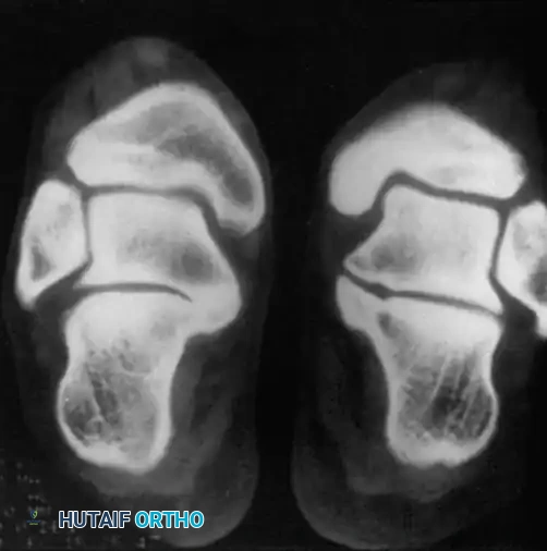
Fig. 2: Talar neoplasms mimicking chronic ankle sprain. Eosinophilic granuloma of the talar body.
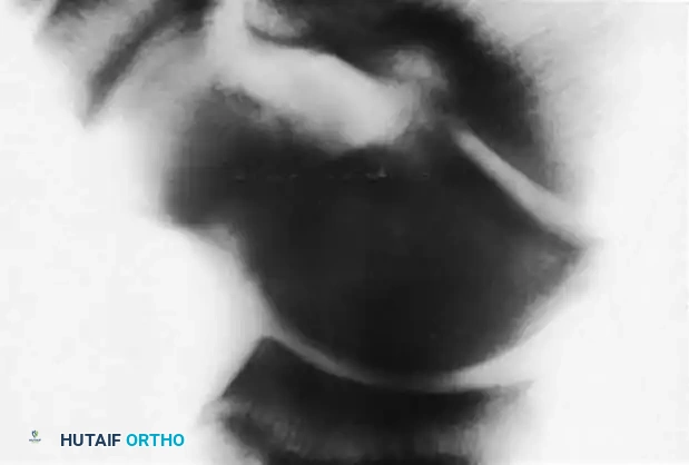
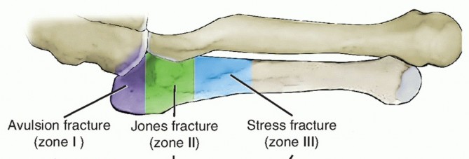
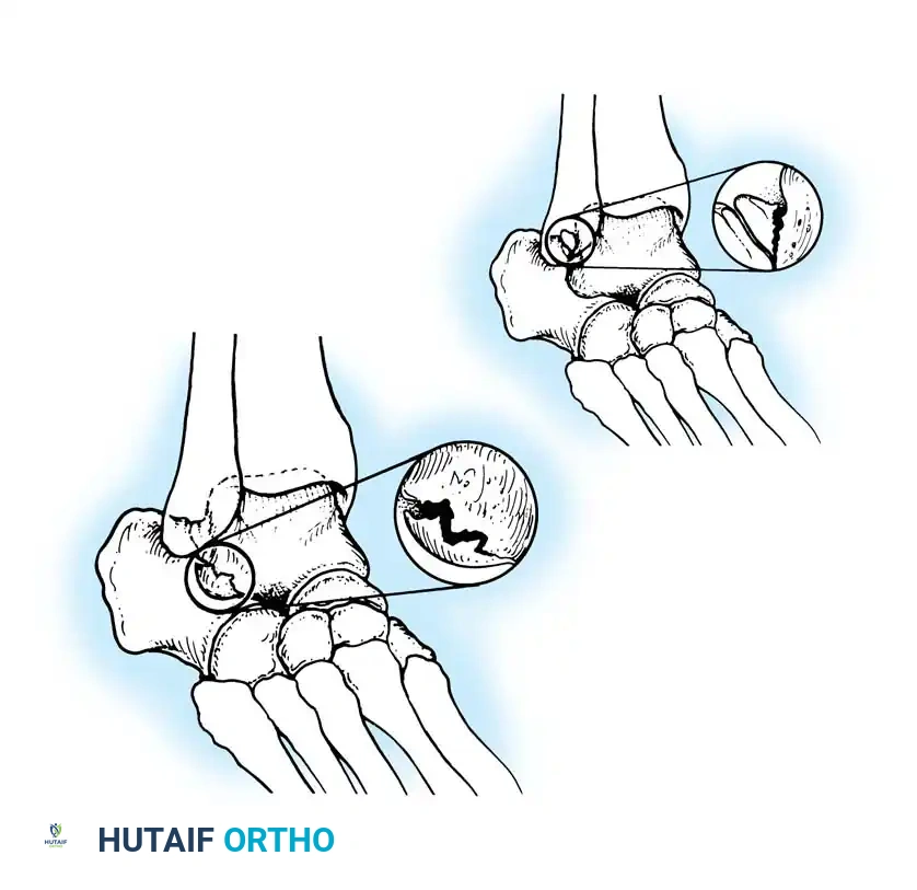
Fig. 3: Avulsion fractures of the talus. Inferolateral and posterolateral process fractures are frequently missed on standard AP and lateral radiographs.
Avulsion Fractures of the Talus
Fractures of the lateral processes of the talus (inferolateral or posterolateral) are often termed "snowboarder's fractures." They occur during forced dorsiflexion and inversion. Standard radiographs frequently miss these lesions due to osseous overlap.
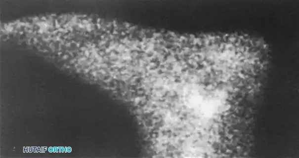
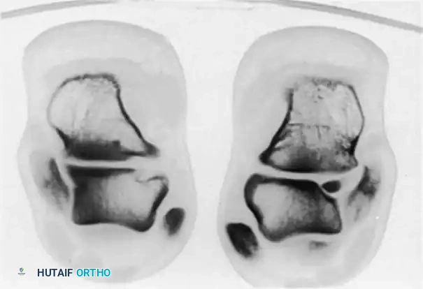
Fig. 4: Diagnostic imaging of an avulsion fracture of the talus. Left: Bone scan demonstrating focal uptake. Right: CT scan confirming the exact morphology of the posterolateral process fracture.
Sinus Tarsi Syndrome
First described by O’Connor in 1958, sinus tarsi syndrome is characterized by persistent pain in the lateral hindfoot—specifically localized to the sinus tarsi—lasting months or years following nonoperative management of an ankle sprain.
Pathoanatomy and Etiology
The sinus tarsi is a conical space between the talus and calcaneus containing the interosseous talocalcaneal ligament, the cervical ligament, adipose tissue, and a rich neurovascular network. The etiology of sinus tarsi syndrome is multifactorial:
* Subtalar Instability: Subtle micro-instability leading to chronic inflammation.
* Soft Tissue Degeneration: Anatomical studies reveal scarring, fat atrophy, and degenerative changes in the soft-tissue elements.
* Proprioceptive Loss: Injury to the neurovascular elements within the cervical ligament may result in a loss of proprioceptive feedback, perpetuating a cycle of microtrauma.
Diagnostic Pitfall: If a targeted injection of a local anesthetic (e.g., bupivacaine) and a corticosteroid into the sinus tarsi fails to provide at least temporary, near-complete relief of symptoms, the diagnosis of sinus tarsi syndrome is highly questionable, and alternative intra-articular pathologies must be sought.
Imaging Findings
Advanced imaging is critical. Taillard et al. utilized subtalar arthrography, noting that an absence of normal microrecesses and an abrupt cutoff of contrast at the interosseous ligament correlated with the syndrome. Modern diagnosis relies heavily on MRI. Klein and Spreitzer demonstrated that MRI findings consistent with fibrosis, chronic synovitis, nonspecific inflammatory changes, and synovial cysts in the sinus tarsi are highly sensitive for the condition.
Surgical Management
When conservative measures (orthotics, injections, physical therapy) fail, surgical intervention is indicated.
* Open Debridement: O’Connor advocated for the excision of the fat pad and resection of the superficial ligamentous floor.
* Ligament-Sparing Techniques: Modern approaches, championed by Clanton and Schon, emphasize preserving the interosseous talocalcaneal and cervical ligaments while meticulously resecting the fibrofatty tissue and extensions from the inferior extensor retinaculum.
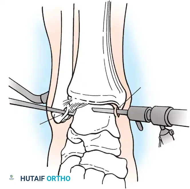
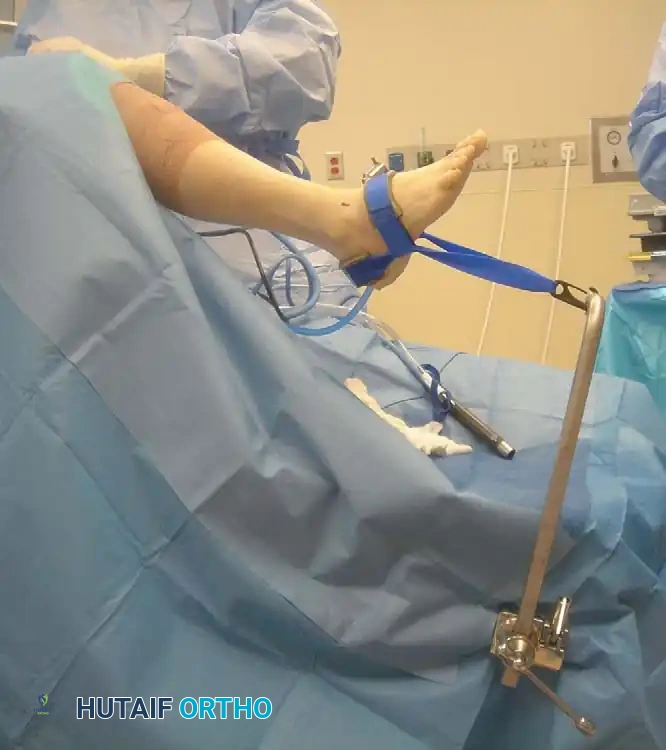
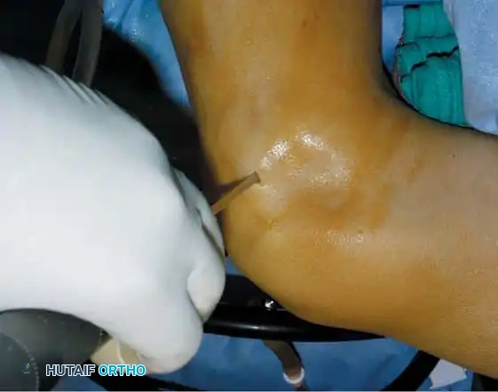
Fig. 5: Intraoperative and arthroscopic views demonstrating the debridement of the sinus tarsi, carefully preserving the structural integrity of the cervical ligament.
Osteochondral Ridges (Anterior and Posterior Impingement Syndromes)
Impingement syndromes of the ankle are characterized by painful mechanical limitations of motion secondary to osseous or soft-tissue hypertrophy.
Anterior Impingement (Athlete's Ankle)
Originally described by O’Donoghue in 1957, anterior impingement is caused by the formation of osteochondral ridges (exostoses) on the anterior lip of the distal tibia and the opposing dorsal neck of the talus.
* Biomechanics: Caused by repetitive, forceful dorsiflexion (e.g., in soccer players or dancers) where the talar neck collides with the anterior tibia. Repeated microtrauma leads to osteophyte formation.
* Clinical Presentation: Aching pain exacerbated by deep dorsiflexion. "Tram track" lesions (parallel chondral grooves) are often visible arthroscopically on the talar dome.
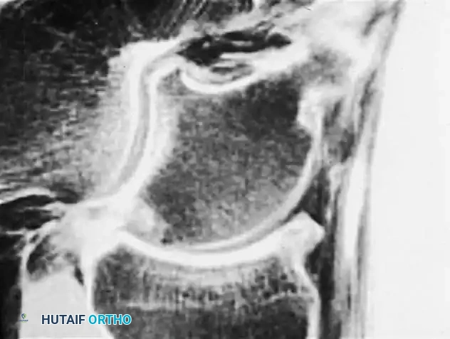
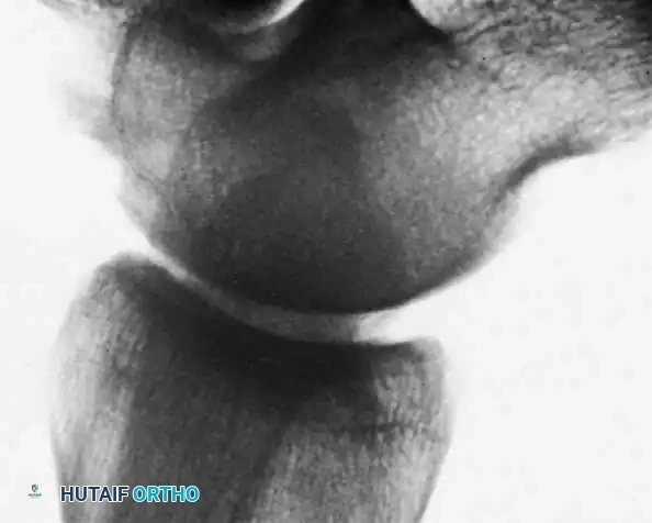
Fig. 6: Anterior impingement syndrome. Left: MRI showing a prominent osteophyte on the distal tibia. Right: Postoperative radiograph following arthroscopic excision of the osteophyte.
Scranton and McDermott Classification
Scranton and McDermott categorized anterior ankle spurs to guide treatment and predict recovery:
* Grade I: Synovial impingement. Radiographs show inflammatory reaction with spurs < 3 mm.
* Grade II: Osteochondral reaction exostosis. Spurs > 3 mm. No talar spur present.
* Grade III: Severe exostosis with or without fragmentation. Secondary spur noted on the dorsum of the talus.
* Grade IV: Pantalocrural osteoarthrotic destruction. Degenerative changes medially, laterally, or posteriorly.
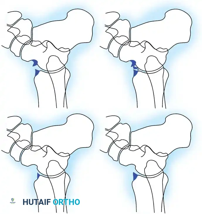
Fig. 7: Scranton and McDermott classification of ankle spurs (Grades I through IV).
Soft-Tissue Impingement (Bassett’s Ligament)
Soft-tissue impingement often occurs anterolaterally following an inversion sprain. Bassett et al. identified that a thickened distal fascicle of the anterior inferior tibiofibular ligament (AITFL) can impinge on the anterolateral aspect of the talus during dorsiflexion, causing localized chondromalacia and chronic pain.
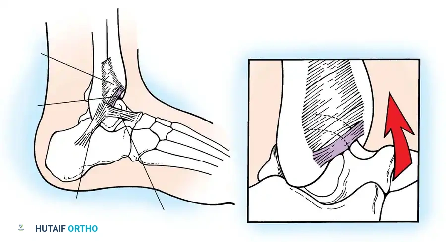
Fig. 8: Lateral aspect of the ankle joint demonstrating the distal fascicle of the AITFL (Bassett's ligament). With dorsiflexion, this thickened fascicle impinges on the anterolateral talus.
🔪 Surgical Technique 42-10: Arthroscopic Treatment of Anterior Impingement
Arthroscopic debridement is the gold standard for symptomatic anterior impingement that has failed at least 6 months of conservative management.
1. Patient Positioning and Preparation:
* Place the patient supine under general or regional anesthesia.
* Apply a well-padded thigh tourniquet.
* Position the foot at the edge of the table. A non-invasive ankle distraction strap is applied to the midfoot and attached to a distraction device.
* Surgical Warning: Excessive distraction can tighten the anterior capsule, making it difficult to access large anterior osteophytes. Distraction may need to be temporarily released during osteophyte resection.
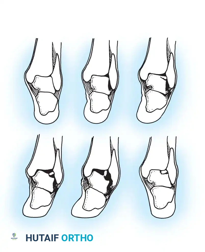
Fig. 9: Patient positioning for ankle arthroscopy utilizing a non-invasive distraction device.
2. Portal Placement:
* Identify the anterior tibial tendon (ATT) and the superficial peroneal nerve (SPN).
* Anteromedial Portal: Created just medial to the ATT at the level of the joint line. Use a #11 blade to incise the skin only, followed by blunt dissection with a mosquito hemostat to avoid the saphenous vein and nerve.
* Anterolateral Portal: Created just lateral to the peroneus tertius tendon. Transillumination from the anteromedial portal can help identify and avoid the branches of the SPN.
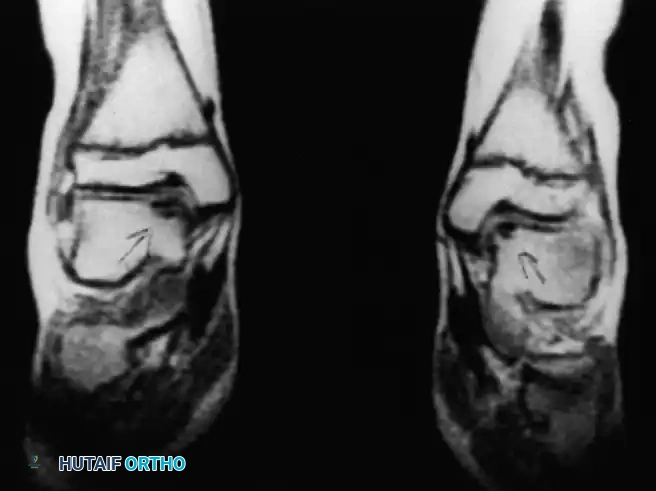
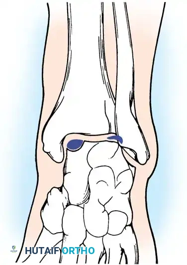
Fig. 10: Establishment of the anteromedial and anterolateral arthroscopic portals. Note the careful blunt dissection to protect neurovascular structures.
3. Diagnostic Sweep and Soft Tissue Debridement:
* Insert a 2.7-mm or 4.0-mm, 30-degree arthroscope.
* Perform a systematic 8-point diagnostic sweep of the joint.
* Identify hypertrophic synovium in the anterolateral gutter. Use a 3.5-mm motorized shaver to perform a localized synovectomy.
* Identify the distal fascicle of the AITFL (Bassett's ligament). If it is thickened and observed to impinge on the talus during dynamic dorsiflexion, resect it using a basket punch or shaver.
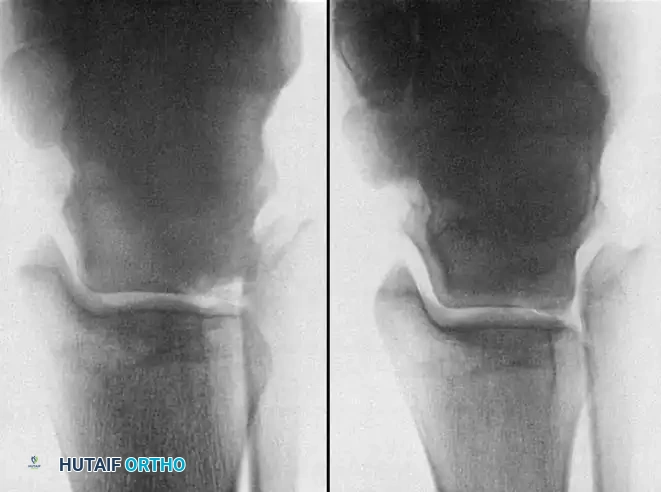
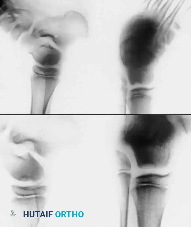
Fig. 11: Arthroscopic views of anterolateral soft-tissue impingement and subsequent shaver debridement.
4. Osteophyte Resection:
* Locate the tibial and talar osteophytes.
* Use a high-speed arthroscopic burr (e.g., 4.0-mm shielded burr) to resect the tibial spur back to the normal contour of the anterior tibial plafond.
* Address the talar neck osteophyte. Plantarflex the ankle to expose the lesion. Burr the exostosis until the talar neck is smooth.
* Dynamic Testing: Release traction and dorsiflex the ankle under direct visualization to confirm that impingement has been completely eliminated.
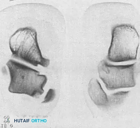
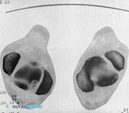
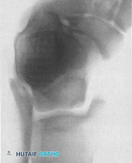
Fig. 12: Sequential arthroscopic burring of the anterior tibial osteophyte. The contour is restored to prevent mechanical block during dorsiflexion.
Postoperative Protocol:
* 0-1 Week: Weight-bearing as tolerated in a controlled ankle motion (CAM) boot. Immediate active and passive range-of-motion (ROM) exercises are initiated to prevent capsular adhesions.
* 1-4 Weeks: Transition to a lace-up ankle brace. Begin proprioceptive training (tilt board) and closed-kinetic-chain strengthening of the gastroc-soleus complex and anterior compartment musculature.
* 6+ Weeks: Gradual return to sports-specific activities.
Osteochondral Lesions of the Talus (OCD)
Osteochondral lesions of the talus (OLT), historically termed osteochondritis dissecans by König in 1888 and later applied to the ankle by Kappis in 1922, represent a localized injury to the articular cartilage and underlying subchondral bone.
Etiology and Biomechanics
The vast majority of OLTs are traumatic in origin, typically resulting from severe inversion injuries.
* Anterolateral Lesions: Caused by inversion and dorsiflexion. The talar dome impacts the fibula, creating a shallow, wafer-shaped shear fracture. These are almost exclusively traumatic and are more likely to become symptomatic and displaced.
* Posteromedial Lesions: Caused by inversion and plantarflexion. The talar dome impacts the tibial plafond, creating a deep, cup-shaped compression fracture. These can be asymptomatic for years and may have a genetic or ischemic component.
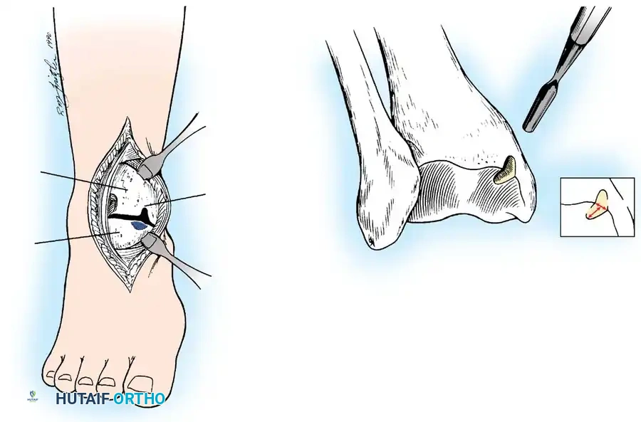
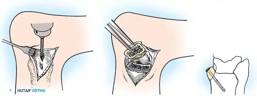
Fig. 13: MRI and corresponding arthroscopic view of a classic posteromedial osteochondral lesion of the talus.
Imaging and Classification
While the Berndt and Harty radiographic classification (Stages I-IV) is historically significant, MRI is the current gold standard for evaluating the size, depth, and stability of the cartilage cap, as well as the presence of subchondral cysts.
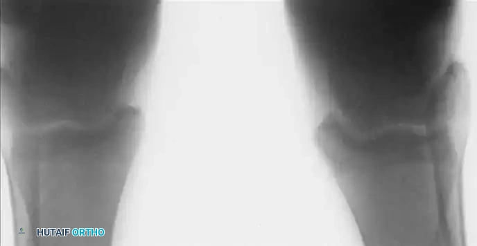
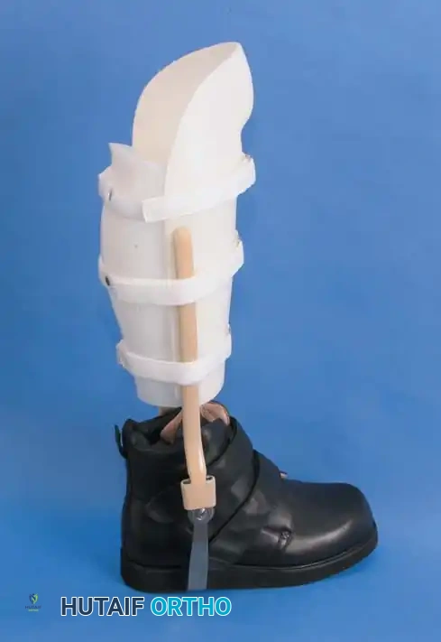
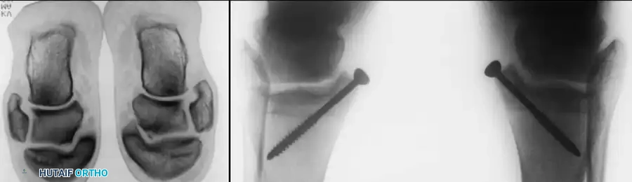
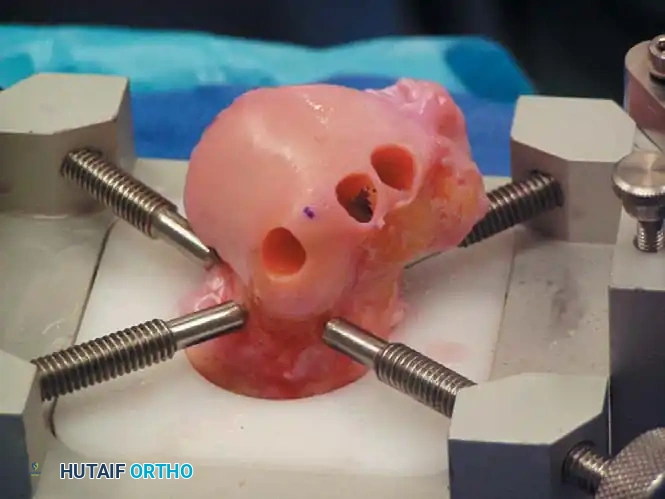
Fig. 14: Advanced imaging modalities (CT and MRI) detailing the extent of subchondral bone involvement and cystic changes in OLTs.
Surgical Management Algorithms
The treatment of OLTs is dictated by the size of the lesion, the status of the overlying cartilage, and whether it is a primary or revision setting.
1. Arthroscopic Bone Marrow Stimulation (Microfracture)
Indicated for primary lesions smaller than 1.5 cm² (or < 15 mm in diameter).
* Technique: The unstable cartilage is debrided to stable, vertical margins using a curette and shaver. The necrotic subchondral bone base is debrided down to bleeding, healthy bone. An arthroscopic awl or K-wire is used to create microfracture holes spaced 2-3 mm apart, penetrating 3-4 mm deep to access the marrow elements. This stimulates the formation of a fibrocartilage (Type I collagen) repair tissue.
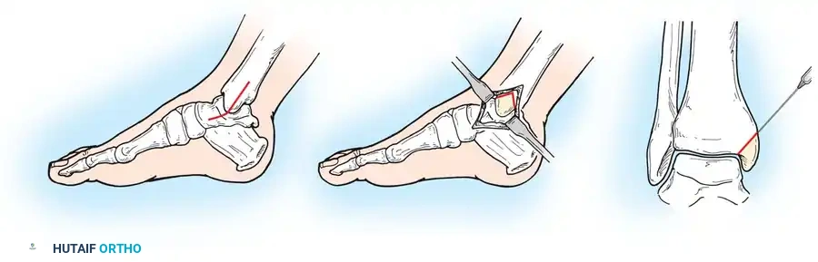
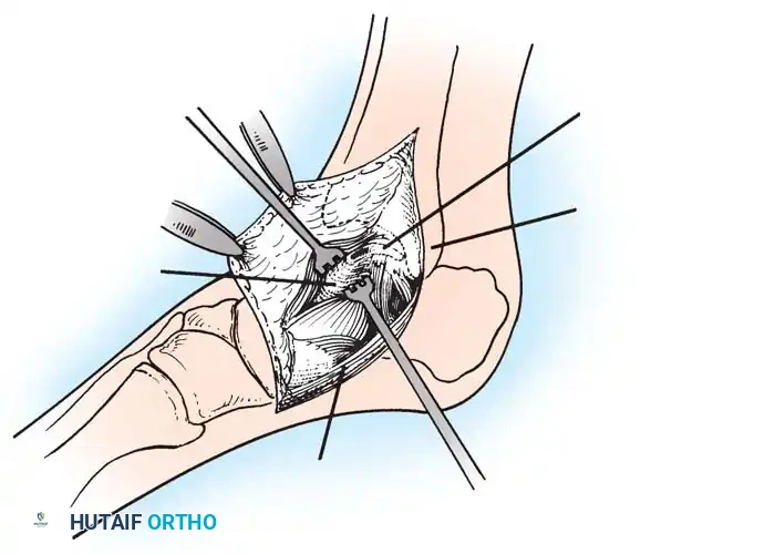
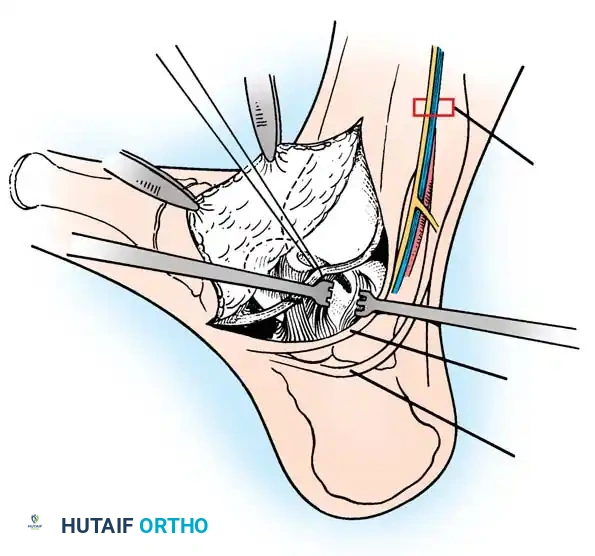
Fig. 15: Arthroscopic debridement and microfracture of an anterolateral talar dome lesion. Note the creation of vertical cartilage walls and the punctate bleeding from the microfracture awl.
2. Osteochondral Autograft Transfer System (OATS)
Indicated for lesions > 1.5 cm², cystic lesions, or those that have failed primary microfracture.
* Technique: This procedure replaces the defect with hyaline cartilage (Type II collagen). Cylindrical osteochondral plugs are harvested from a non-weight-bearing portion of the ipsilateral knee (e.g., the lateral femoral condyle periphery) and press-fit into the prepared defect on the talus.
* Approach: Anterolateral lesions can often be accessed via a small arthrotomy. Posteromedial lesions frequently require a medial malleolar osteotomy for perpendicular access.
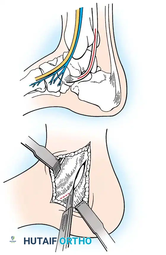
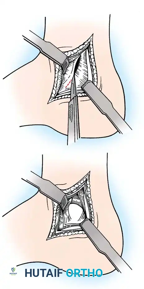
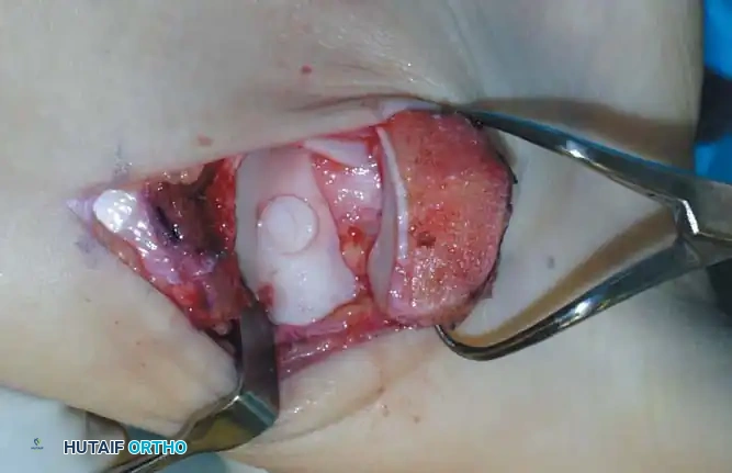
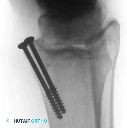
Fig. 16: Preparation for an OATS procedure. A medial malleolar osteotomy is performed to gain perpendicular access to a large posteromedial lesion.
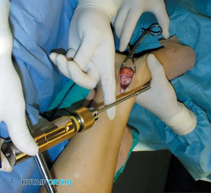
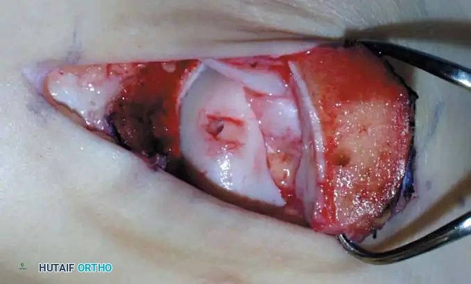
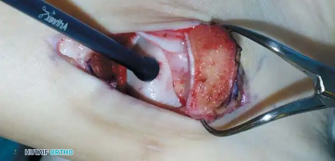
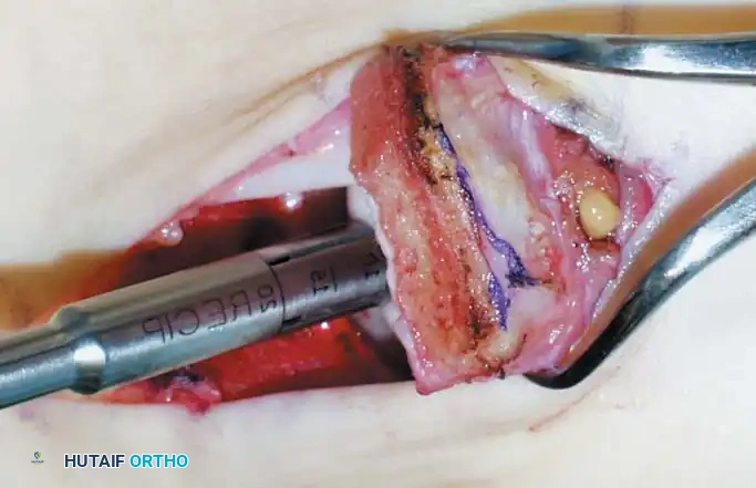
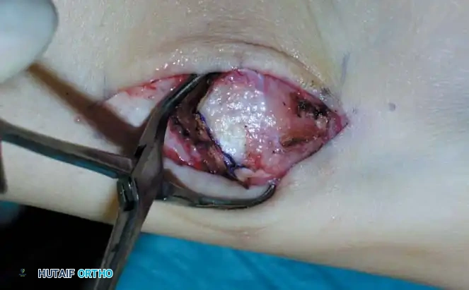
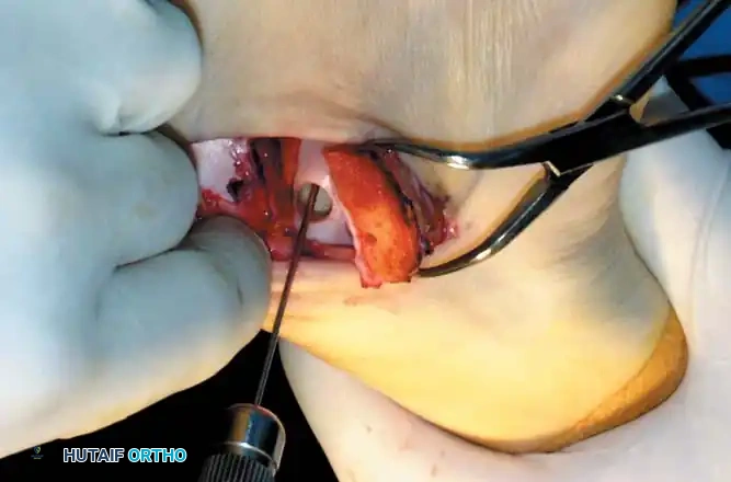
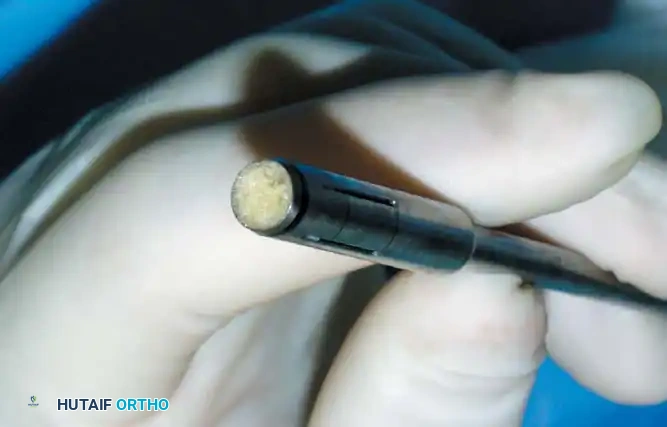
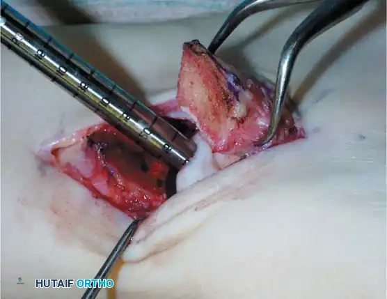
Fig. 17: Step-by-step OATS technique. The recipient site is cored out, and the donor plug from the knee is carefully impacted into the talar defect, ensuring flush alignment with the surrounding native cartilage.
3. Structural Allograft and Advanced Techniques
For massive, uncontained lesions or severe cystic degeneration, structural fresh osteochondral allografts are utilized. These require meticulous size-matching and rigid internal fixation.

You Might Also Like