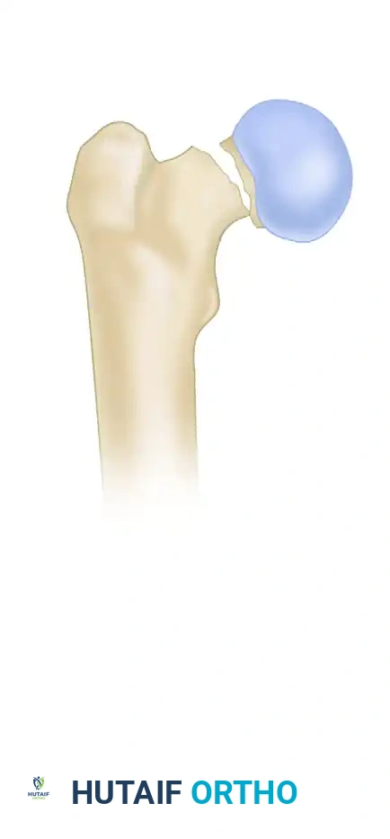
INTRODUCTION TO FEMORAL NECK FRACTURE FIXATION
Femoral neck fractures represent a critical challenge in orthopedic trauma, demanding precise surgical execution to preserve the native hip joint and prevent devastating complications such as avascular necrosis (AVN) and nonunion. While arthroplasty is often the treatment of choice for displaced fractures in the elderly, internal fixation with cannulated screws remains the gold standard for undisplaced fractures (Garden I and II) across all age groups, as well as for displaced fractures (Garden III and IV) in physiologically young patients where joint preservation is paramount.
The goal of multiple cannulated screw fixation is to provide stable, compression-yielding osteosynthesis that resists the shear and rotational forces acting across the femoral neck. This masterclass details the textbook-level surgical technique, biomechanical principles, and critical pitfalls associated with the fixation of femoral neck fractures using cannulated screws.
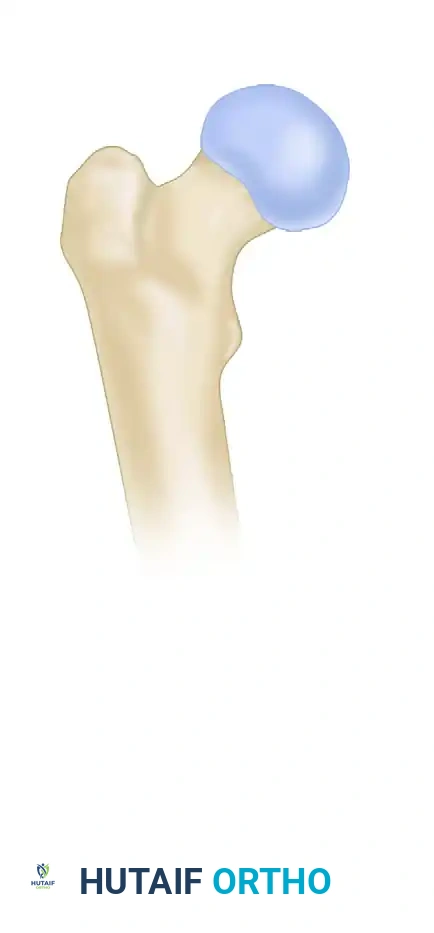
SURGICAL ANATOMY AND BIOMECHANICS
A profound understanding of the proximal femoral osseous architecture and its precarious vascular supply is mandatory before undertaking internal fixation.
Vascular Considerations
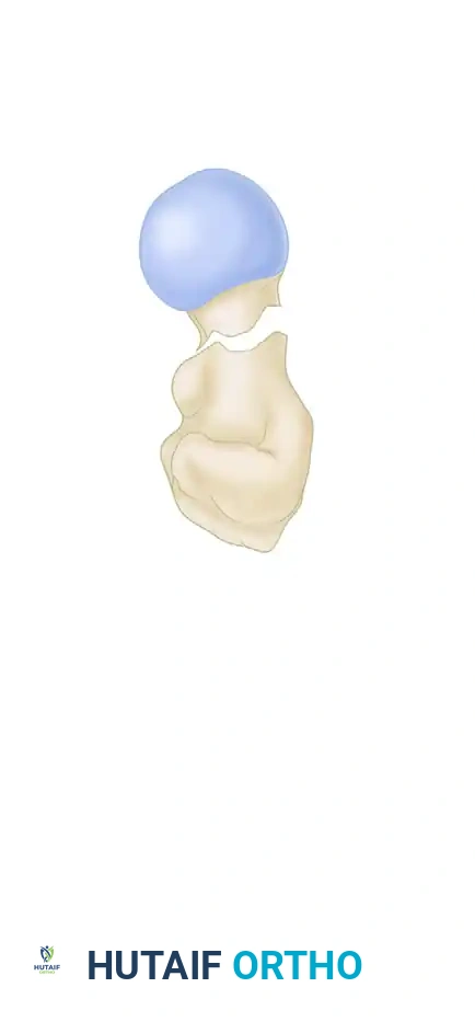
The primary blood supply to the femoral head is derived from the medial circumflex femoral artery (MCFA), specifically its lateral epiphyseal branches. These vessels traverse the posterosuperior aspect of the femoral neck. Surgical approaches and implant placement must respect this anatomy; errant superior or posterior guide pin placement can cause iatrogenic vascular insult, drastically increasing the risk of postoperative AVN.
Lowell's "S" Curve and Anatomical Alignment
Radiographic assessment of anatomical alignment relies heavily on the restoration of normal osseous contours. As described by Lowell, the concave outline of the femoral neck meets the convex outline of the femoral head in an "S" or reversed "S" curve superiorly, inferiorly, anteriorly, and posteriorly.
Clinical Pearl: Restoration of these "S" signs on both the anteroposterior (AP) and lateral fluoroscopic views is the definitive radiographic indicator of anatomical alignment. Acceptance of a reduction that fails to restore these curves, particularly one leaving the fracture in varus, significantly increases the risk of mechanical failure.
Biomechanics of Screw Configuration
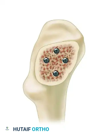
The standard construct utilizes three partially threaded screws (typically 6.5 mm or 7.0 mm) placed in an inverted triangle configuration.
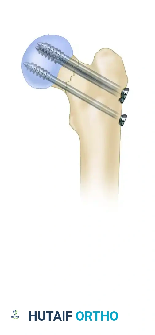
- Inferocentral Screw: Acts as the primary load-bearing strut. It must be placed adjacent to the calcar femorale to provide inferior cortical support and resist varus displacement.
- Posterosuperior and Anterosuperior Screws: These screws provide rotational stability and anterior/posterior cortical support.
Surgical Warning: In a biomechanical model, screw configuration has been shown to heavily influence the occurrence of iatrogenic subtrochanteric femoral fractures. Fractures fixed with an apex-distal configuration (where the inferior screw is the most distal) exhibit a significantly greater load to failure compared to an apex-proximal configuration. Always strive for an apex-distal inverted triangle to minimize stress risers in the lateral cortex.
INDICATIONS AND PREOPERATIVE PLANNING
Patient selection and preoperative radiographic analysis are the first steps toward a successful outcome.
Indications for Cannulated Screw Fixation
- Garden I and II Fractures: Undisplaced or valgus-impacted fractures in patients of all ages.
- Garden III and IV Fractures: Displaced fractures in physiologically young patients (typically under 60-65 years of age) where native joint preservation is critical.
- Basicervical Fractures: Though some surgeons prefer a dynamic hip screw (DHS) for basicervical patterns, multiple cannulated screws can be utilized if anatomical reduction is achieved and bone quality is excellent.
Preoperative Imaging
Standard AP pelvis and cross-table lateral radiographs of the affected hip are required. Assess the degree of comminution, particularly along the posterior neck, as significant posterior comminution may dictate the need for a four-screw construct.
PATIENT POSITIONING AND SETUP
Meticulous patient positioning is arguably the most critical non-operative step. Poor positioning leads to inadequate fluoroscopic visualization, which inevitably compromises screw trajectory.
- Table Selection: Place the patient supine on a radiolucent fracture table.
- Leg Positioning: We typically "scissor" the lower extremities to allow unimpeded lateral fluoroscopy. The unaffected hip is extended and dropped posteriorly relative to the injured side. Alternatively, the unaffected leg can be placed in a well-leg holder in a lithotomy position (flexed, abducted, and externally rotated).
- C-Arm Setup: Position the fluoroscopy unit between the patient's legs (if scissored) or entering from the contralateral side. Ensure that perfect AP and true lateral views of the femoral neck can be obtained with minimal adjustment of the C-arm base.
CLOSED REDUCTION TECHNIQUES
Anatomical reduction is non-negotiable. Fixation of a femoral neck fracture in varus or retroversion leads to unacceptably high rates of nonunion and implant failure.
The Whitman Maneuver
Attempt closed reduction using the Whitman technique or a similar reduction maneuver:
1. Apply longitudinal traction to the injured limb to disimpact the fracture fragments and restore leg length.
2. While maintaining traction, internally rotate the limb (typically 15 to 20 degrees) to correct the external rotation deformity and align the femoral neck with the shaft.
3. Abduct the limb slightly to lock the fracture fragments under tension.
Assessing the Reduction
Evaluate the reduction using fluoroscopy in both planes.
- AP View: Look for a normal neck-shaft angle (130-135 degrees) or slight valgus. Varus is unacceptable. Verify the restoration of Lowell's superior and inferior "S" curves.
- Lateral View: Ensure there is no anterior or posterior angulation (sagittal tilt). The anterior and posterior "S" curves must be continuous.
Pitfall: If closed reduction is unsuccessful after two or three gentle attempts, do not persist, as repeated aggressive maneuvers can further damage the tenuous blood supply. Proceed immediately to an open reduction via a Watson-Jones or Smith-Petersen approach.
SURGICAL TECHNIQUE: STEP-BY-STEP
1. Incision and Surgical Approach
- Use fluoroscopy in both planes to localize the starting point for the inferocentral wire.
- Make a longitudinal skin incision extending 2 to 3 cm proximally from the planned starting point.
- Split the fascia lata in line with the skin incision.
- Use a Cobb elevator to gently split the fibers of the vastus lateralis muscle longitudinally down to the lateral cortex of the femur. Sweep the muscle belly anteriorly and posteriorly to expose the bone.
2. Inferocentral Guide Wire Placement
The placement of the first guide wire dictates the success of the entire construct.
- Place the inferocentral wire in perfect position on both AP and lateral views.
- Trajectory: The wire should run parallel to and immediately superior to the calcar femorale on the AP view, and centrally within the neck on the lateral view.
- Starting Point: Make absolutely sure not to begin below the level of the lesser trochanter. Starting below this level creates a severe stress riser in the subtrochanteric region.
- Depth: Advance the wire into the subchondral bone of the femoral head, stopping just short of the articular surface.
Clinical Pearl: Placing a secondary, blunt guidewire percutaneously along the anterior aspect of the femoral neck can be highly helpful in determining the appropriate anteversion before drilling the inferocentral wire into the bone.
3. Superior Guide Wire Placement
- Once the first guide pin is in perfect position, use a parallel drill guide to place the remaining pins.
- Place the posterosuperior pin, followed by the anterosuperior pin.
- The goal is to obtain maximal posterior and anterior cortical support within the femoral neck. The pins should be spread as widely as possible within the neck while remaining entirely intraosseous.
- Advance these threaded guide pins just short of the articular surface.
- Fluoroscopic Check: Rotate the C-arm through a full arc (or internally/externally rotate the leg slightly if off traction) to be absolutely certain no pins have violated the articular surface.
4. Screw Measurement and Preparation
- To determine the appropriate screw length, measure the length of the guide pin using the depth gauge.
- Crucial Step: Subtract 5 mm from the measured length. This allows for fracture compression during screw insertion without the risk of the screw tip penetrating the joint space.
- Self-drilling, self-tapping partially threaded screws (6.5 mm or 7.0 mm) are generally used.
- In patients with dense, young cortical bone, predrilling of the outer lateral cortex over the guide wire is often necessary to prevent the screw from binding and inadvertently distracting the fracture.
- Washers: Washers should be used where space permits, particularly in osteopenic bone, to prevent the screw head from sinking through the lateral cortex.
5. Screw Insertion and Final Fluoroscopic Verification
- Insert the screws over the guide wires.
- Sequence of tightening: Advance all three screws until they are just engaging the lateral cortex. Then, sequentially tighten them to achieve uniform compression across the fracture site.
- Release traction slightly during final tightening to allow the fracture to compress dynamically.
- Remove the guide wires and obtain final AP and lateral radiographs. Ensure the threads of all screws have completely bypassed the fracture line and reside entirely within the femoral head epiphysis; otherwise, interfragmentary compression cannot occur.
Alternative Percutaneous Technique
In strictly undisplaced fractures, an alternative percutaneous approach may be utilized. Place the guide pins directly through the skin under fluoroscopic guidance. Once the pins are perfectly positioned, make an approximately 1-cm stab incision around each guide pin, deepen it through the fascia and vastus lateralis using a hemostat, and insert the screws.
ADVANCED FIXATION: THE DIAMOND CONFIGURATION
While the three-screw inverted triangle is the standard of care, specific fracture morphologies require augmented fixation.
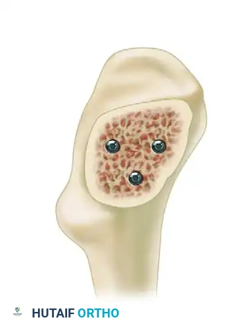
A fourth screw, creating a diamond configuration, may be necessary in patients with significant posterior comminution.
- Rationale: Posterior comminution represents a loss of the posterior cortical buttress, making the construct highly susceptible to retroversion and failure under physiological loads.
- Execution: The fourth screw is placed centrally and posteriorly to provide additional structural rigidity and rotational control. Ensure that the addition of a fourth screw does not crowd the lateral cortex excessively, which could compromise the integrity of the lateral wall.
COMPLICATIONS AND PITFALLS
1. Subtrochanteric Femoral Fracture
Extreme care must be taken in the placement of guide pins. Inaccurate passage of the pins—specifically, multiple drilling attempts that create cortical defects, or attempts placed below the level of the lesser trochanter—has been strongly associated with iatrogenic subtrochanteric femoral fractures. As noted previously, utilizing an apex-distal configuration maximizes the load to failure and protects the subtrochanteric region.
2. Avascular Necrosis (AVN)
AVN is a biological complication resulting from the disruption of the medial circumflex femoral artery at the time of injury, or iatrogenically during surgery. Rates of AVN increase with the degree of initial displacement and the time to surgery. Anatomical reduction and avoiding superior/posterior capsular stripping are the best preventative measures.
3. Nonunion and Screw Cutout
Nonunion occurs in up to 15% of displaced fractures treated with internal fixation. It is primarily driven by poor reduction (varus alignment) or failure to achieve interfragmentary compression (e.g., screw threads crossing the fracture site). Screw cutout into the joint is typically a secondary mechanical failure resulting from nonunion or profound osteopenia.
POSTOPERATIVE PROTOCOL
- Weight-Bearing: Postoperative weight-bearing protocols remain debated. For young patients with excellent bone quality and a stable construct, immediate weight-bearing as tolerated (WBAT) is often permitted. In elderly or osteopenic patients, restricted weight-bearing (toe-touch or partial) for 6 to 8 weeks may be advised, though compliance is often poor.
- DVT Prophylaxis: Chemical and mechanical deep vein thrombosis (DVT) prophylaxis is mandatory, tailored to the patient's risk profile.
- Follow-up: Serial radiographs (AP and lateral) should be obtained at 2 weeks, 6 weeks, 3 months, 6 months, and 1 year to monitor for fracture union, hardware migration, and late-onset AVN.
By adhering strictly to these biomechanical principles, respecting the vascular anatomy, and executing precise surgical steps, orthopedic surgeons can maximize the success rates of cannulated screw fixation for femoral neck fractures.
