Surgical Anatomy of the Spinal Cord, Nerve Roots, and Vertebral Pedicles
Key Takeaway
Understanding the surgical anatomy of the spinal cord and vertebral pedicles is paramount for safe spinal instrumentation. This comprehensive guide details the morphological characteristics of cervical, thoracic, and lumbar pedicles, alongside the neurovascular topography of the spinal cord. Mastery of these anatomical relationships, including pedicle trajectories and spinal cord blood supply, minimizes iatrogenic injury and optimizes outcomes in complex spinal reconstructions and degenerative spine surgery.
SURGICAL ANATOMY OF THE SPINAL CORD AND NERVES
A profound understanding of the neuroanatomy and osteology of the spine is the foundation of safe and effective operative orthopaedics. The spinal cord, nerve roots, and their enveloping structures dictate the surgical corridors available during decompression, deformity correction, and spinal instrumentation.
Gross Anatomy and Meningeal Envelopes
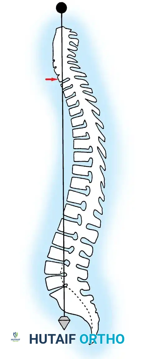
The spinal cord is significantly shorter than the bony vertebral column, a discrepancy arising from the differential growth rates of the central nervous system and the axial skeleton during embryogenesis. In adults, the spinal cord typically terminates as the conus medullaris at the level of the intervertebral disc between the first and second lumbar vertebrae (L1-L2). In neonates, the termination is lower, typically at the third lumbar vertebra (L3). From the apex of the conus medullaris, a fibrous band of connective tissue known as the filum terminale extends distally, anchoring the spinal cord to the dorsum of the first coccygeal segment.
The spinal cord is protected by three distinct meningeal layers:
* Pia Mater: The innermost layer, intimately adherent to the neural tissue.
* Arachnoid Mater: A delicate, avascular web-like membrane.
* Dura Mater: The robust, outermost fibrous layer.
The subarachnoid space, located between the pia and arachnoid membranes, contains the cerebrospinal fluid (CSF), which provides buoyancy and mechanical protection to the neural elements.
Somatotopic Organization of Spinal Tracts
The spinal cord exhibits distinct fusiform enlargements in the cervical and lumbar regions, corresponding to the extensive neural networks required to innervate the upper and lower extremities via the brachial and lumbosacral plexuses, respectively.
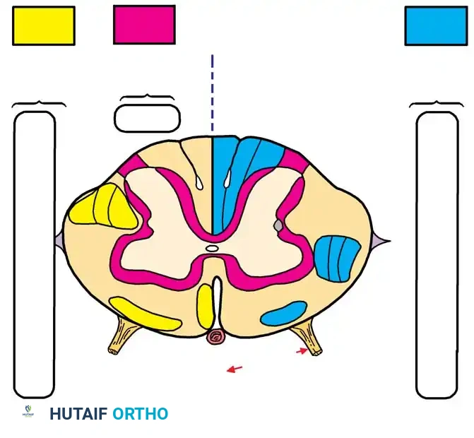
Within the spinal cord parenchyma, ascending (sensory) and descending (motor) nerve fibers are organized into highly specific tracts. A critical surgical concept is the somatotopic lamination of these pathways. Typically, the cervical tracts are located centrally, while the thoracic, lumbar, and sacral tracts are positioned progressively toward the periphery.
This precise anatomical arrangement explains the clinical presentation of specific spinal cord syndromes. For instance, in Central Cord Syndrome (often resulting from hyperextension injuries in a stenotic cervical spine or a central syrinx), the centrally located cervical motor tracts are disproportionately affected. This results in profound motor weakness in the upper extremities with relative sparing of the lower extremities and sacral function.
Key tracts include:
* Lateral Corticospinal Tract (Descending): Responsible for ipsilateral skilled voluntary movement.
* Anterior Corticospinal Tract (Descending): Contributes to contralateral skilled movement.
* Lateral Spinothalamic Tract (Ascending): Transmits contralateral pain and temperature sensation.
* Dorsal Columns (Fasciculus Gracilis and Cuneatus) (Ascending): Transmit ipsilateral proprioception, vibration, and fine touch.
Spinal Nerve Root Anatomy
Spinal nerves exit the vertebral canal at each respective level, but their nomenclature and exit strategies vary by region:
* Cervical Spine (C1-C7): Spinal nerves exit above the pedicle for which they are named. For example, the C6 nerve root exits through the C5-C6 neural foramen.
* C8 Nerve Root: Exits the foramen between the C7 and T1 pedicles.
* Thoracolumbar Spine (T1-L5): All spinal nerves caudal to C8 exit the foramen below the pedicle for which they are named. For example, the L4 nerve root exits the L4-L5 neural foramen.
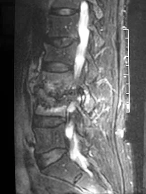
Because the spinal cord terminates at L1-L2, the lumbar and sacral nerve roots must travel a considerable distance vertically within the dural sac before exiting their respective foramina, forming the cauda equina.
Each spinal level gives off a dorsal (sensory) root and a ventral (motor) root, which merge to form the mixed spinal nerve. The dorsal root ganglion (DRG), housing the cell bodies of sensory neurons, is typically located within the superior aspect of the neural foramen.
Clinical Pearl: The dorsal root ganglion is exquisitely sensitive to mechanical compression, thermal injury, and manipulation. Retraction of the DRG during transforaminal lumbar interbody fusion (TLIF) or microdiscectomy can precipitate severe, intractable dysesthetic leg pain.
VASCULAR ANATOMY OF THE SPINAL CORD
The vascular supply to the spinal cord is complex and highly variable, making it susceptible to ischemic injury during major spinal deformity corrections or aortic surgeries. Dommisse's seminal work established several constant principles governing this vascularity:
- Three Primary Longitudinal Vessels: The cord is supplied by one anterior median longitudinal arterial trunk (supplying the anterior two-thirds of the cord) and a pair of posterolateral trunks (supplying the posterior one-third).
- Metabolic Demand: The longitudinal arterial trunks are largest in the cervical and lumbar enlargements due to the high metabolic demands of the abundant gray matter in these regions. The thoracic region has a comparatively tenuous blood supply.
- Radicular Feeders: The longitudinal vessels are reinforced by medullary feeder (radicular) arteries. There are typically 2 to 17 anterior radicular arteries and 6 to 25 posterior ones. In the cervical spine, the vertebral arteries supply 80% of these feeders. In the thoracolumbar spine, they arise from intercostal and lumbar arteries. The most prominent of these is the Artery of Adamkiewicz (Arteria Radicularis Magna), which typically arises on the left side between T8 and L1 and provides the dominant blood supply to the lower two-thirds of the spinal cord.
ANATOMY AND MORPHOLOGY OF THE VERTEBRAL PEDICLES
The vertebral pedicles are robust, tube-like cortical and cancellous bone structures that bridge the anterior column (vertebral body) and the posterior elements (lamina, facets, spinous process). They serve as the strongest point of attachment for spinal instrumentation. However, their complex three-dimensional morphology requires precise surgical navigation to avoid catastrophic neurovascular complications.
Cervical Pedicle Morphology
Placement of pedicle screws in the subaxial cervical spine (C3-C7) is technically demanding and carries a higher risk profile than lateral mass fixation or anterior plating.
Morphometric studies by Karaikovic et al. utilizing computed tomography (CT) have defined the critical parameters of cervical pedicles:
* Diameter: C2 and C7 possess the largest mean interdiameters, making them the most accommodating for screw fixation. Conversely, C3 has the smallest mean interdiameter. Screws placed in C3, C4, and C5 typically require smaller diameters (< 4.5 mm) and meticulous trajectory planning.
* Shape: The outer pedicle width-to-height ratio increases from C2 to C7. Upper cervical pedicles (C2-C4) are vertically elongated (elliptical), whereas lower cervical pedicles (C6-C7) are more rounded.
* Angulation: Cervical pedicles angle medially at all levels. The maximum medial angulation occurs at C5, while the least medial angulation is observed at C2 and C7. In the sagittal plane, pedicles slope upward at C2 and C3, are relatively parallel to the axial plane at C4 and C5, and angle downward at C6 and C7.
Surgical Warning: The Vertebral Artery
The vertebral artery courses through the transverse foramina from C6 to C2 and is at significant risk during cervical pedicle screw placement. The lateral cortex of the cervical pedicle is exceptionally thin, offering minimal resistance to a misdirected drill or tap. In contrast, the medial cortex (adjacent to the spinal cord) is nearly twice as thick. A lateral breach can result in catastrophic vertebral artery hemorrhage or pseudoaneurysm, while a medial breach risks spinal cord injury.
Thoracic Pedicle Morphology
The thoracic pedicle is a convoluted, three-dimensional structure composed of a cortical shell filled with cancellous bone (62% to 79% by volume).
Extensive morphometric analyses by Zindrick, Saillant, and Panjabi have demonstrated that thoracic pedicles are narrowest in the horizontal plane at T5. In the sagittal plane, the widest pedicles are found at T11, and the narrowest at T1.
Biomechanical studies by Kothe et al. revealed that the cortical density of the thoracic pedicle is asymmetrical. The medial wall (protecting the dural sac) is significantly thicker and denser than the lateral wall (adjacent to the pleura and rib head). Consequently, iatrogenic pedicle fractures during screw insertion most commonly occur laterally. While a lateral breach in the thoracic spine may result in a pneumothorax or intercostal neuralgia, a medial breach can cause irreversible spinal cord injury.
Lumbar Pedicle Morphology
The lumbar pedicles are the largest and most frequently instrumented in the spine. They are widest at L5 and progressively narrow as one moves cephalad toward the thoracolumbar junction.
In the horizontal plane, the pedicle angle increases progressively from L1 to L5, with L5 exhibiting the greatest medial convergence (often up to 30 degrees). In the sagittal plane, the pedicles angle caudad at L5, are relatively neutral at L4, and angle cephalad from L3 to T1.
The neural foramen lies immediately inferior to the pedicle. The exiting lumbar nerve root is situated in the upper third of the foramen, directly beneath the inferior cortex of the pedicle. Therefore, an inferior or medial pedicle breach is highly dangerous and likely to cause radiculopathy or dural tears, whereas a superior or lateral breach is relatively more forgiving.
PRINCIPLES OF PEDICLE SCREW INSERTION: SURGICAL APPROACH
Accurate pedicle screw placement requires a synthesis of preoperative imaging, intraoperative anatomical landmarks, and fluoroscopic or stereotactic navigation.
Preoperative Planning
High-quality anteroposterior (AP) and lateral radiographs, combined with fine-cut axial CT scans, are mandatory. The surgeon must measure the pedicle diameter, calculate the medial and sagittal trajectories, and assess for anatomical anomalies such as dysplastic pedicles or rotational deformities.
Surgical Localization Techniques
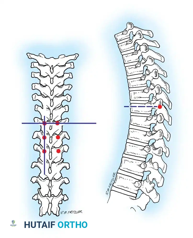
Three primary anatomical landmark techniques are utilized to identify the pedicle starting point in the thoracolumbar spine:
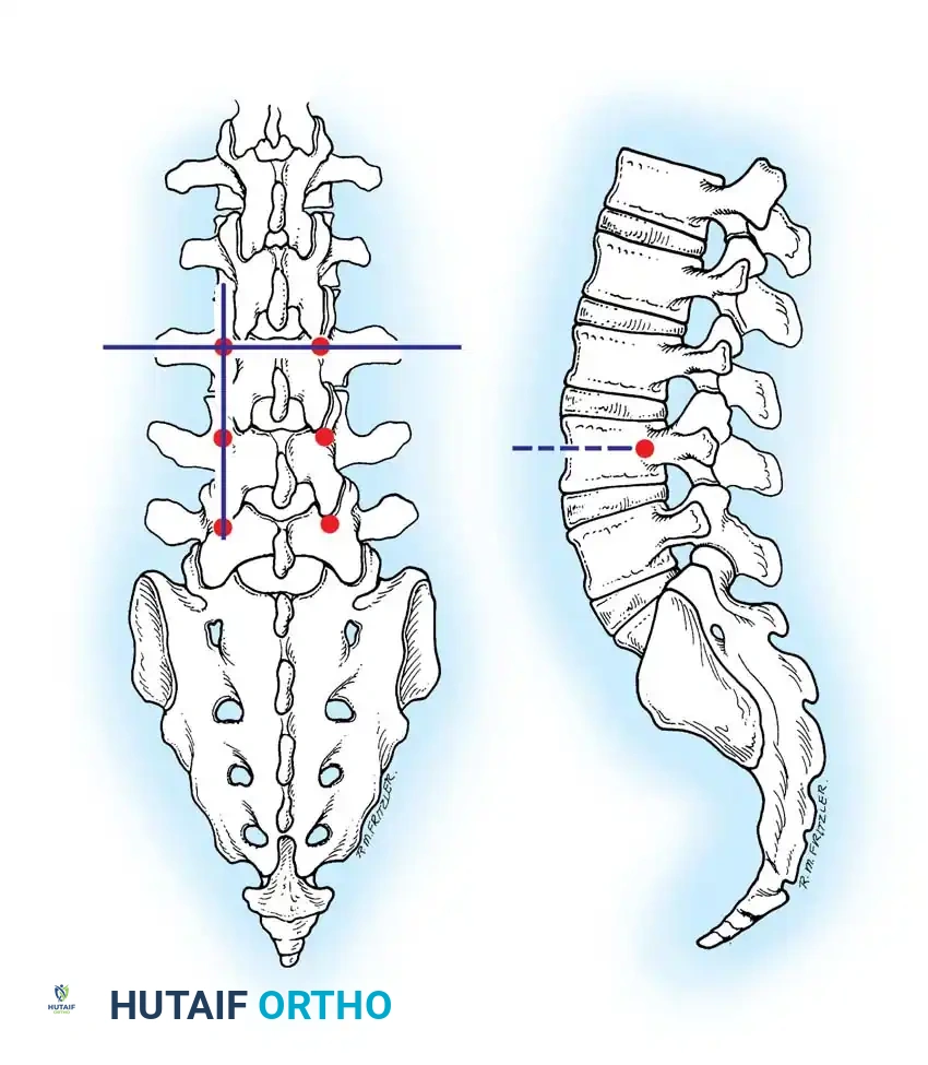
- The Intersection Technique: This is the most universally applied method. A vertical line is dropped from the lateral aspect of the superior articular facet. A horizontal line is drawn bisecting the transverse process. The intersection of these two lines marks the dorsal projection of the pedicle axis.
- The Pars Interarticularis Technique: The pars interarticularis is the cortical bridge connecting the superior and inferior articular processes. The junction where the pars meets the base of the transverse process serves as a reliable starting point, particularly when facet hypertrophy obscures the intersection landmarks.
- The Mammillary Process Technique: The mammillary process is a small bony prominence located at the base of the transverse process and the superior articular facet. This serves as a starting point, though it is generally more lateral than the intersection technique, requiring a greater degree of medial angulation during trajectory preparation.
Step-by-Step Pedicle Preparation and Screw Insertion
- Exposure: Perform meticulous subperiosteal dissection to expose the spinous processes, laminae, facet joints, and the entire transverse process. Complete visualization of the lateral border of the pars and the base of the transverse process is critical.
- Cortical Breach: Use a high-speed burr or a sharp awl to decorticate the starting point, penetrating the dorsal cortex to expose the underlying cancellous bone of the pedicle tract.
- Cannulation: Advance a curved, blunt-tipped pedicle probe (e.g., Lenke gearshift) down the cancellous core of the pedicle. The curve should initially face laterally to avoid medial wall perforation. Once the probe passes the base of the pedicle and enters the vertebral body, it is rotated 180 degrees so the curve faces medially, allowing safe advancement toward the anterior third of the vertebral body.
- Palpation: Remove the probe and insert a flexible ball-tip feeler. The surgeon must systematically palpate the five bony boundaries of the tract: the medial, lateral, superior, and inferior walls, as well as the floor (anterior cortex of the vertebral body). Any soft tissue felt indicates a cortical breach.
- Tapping: Tap the pedicle tract. In osteoporotic bone, undertapping by 1 mm relative to the planned screw diameter is recommended to maximize insertional torque and pull-out strength.
- Screw Insertion: Insert the appropriate diameter and length pedicle screw following the established trajectory.
- Verification: Confirm placement using orthogonal fluoroscopy (AP and lateral views). In the AP view, the screw tip should not cross the medial border of the pedicle until it has passed the posterior vertebral body wall on the lateral view.
POSTOPERATIVE PROTOCOLS AND COMPLICATION MANAGEMENT
Postoperative management following spinal instrumentation relies on rigorous neurological monitoring.
Intraoperative Neuromonitoring (IONM)
Somatosensory evoked potentials (SSEPs) and motor evoked potentials (MEPs) are standard. Additionally, stimulated electromyography (sEMG) of the pedicle screws is highly recommended. A stimulation threshold greater than 10-15 mA generally indicates an intact bony pedicle wall. A threshold below 8 mA strongly suggests a medial or inferior cortical breach with the screw in direct proximity to the neural elements, necessitating immediate screw removal, re-palpation, and redirection.
Managing Pedicle Breaches
If a medial breach is identified intraoperatively, the screw must be removed. If the breach is small and the patient's neuromonitoring remains stable, the trajectory can be redirected more laterally. If a CSF leak occurs due to a dural tear from a medial breach, primary repair (if accessible) or the application of dural sealants and a fascial patch is required. Lateral breaches in the thoracic spine require careful assessment for pleural violation; if a pneumothorax is suspected, a postoperative chest radiograph is mandatory, and a chest tube may be indicated.
Mastery of the intricate surgical anatomy of the spinal cord and vertebral pedicles is non-negotiable. By adhering to strict morphometric principles and employing meticulous surgical technique, the orthopaedic surgeon can achieve rigid spinal fixation while safeguarding the delicate neurovascular structures of the axial skeleton.
You Might Also Like