Masterclass in Lag Screw Fixation: Principles, Biomechanics, and Surgical Technique
Key Takeaway
Lag screw fixation is a fundamental orthopedic technique designed to achieve absolute stability through interfragmentary compression. By meticulously preparing a gliding hole in the near cortex and a threaded hole in the far cortex, surgeons can generate significant compressive forces across the fracture plane. This technique is paramount for intra-articular fractures, ensuring anatomical reduction, facilitating early mobilization, and minimizing the risk of post-traumatic osteoarthritis.
Introduction to Screw Fixation and the Lag Principle
Screw fixation remains one of the most fundamental and ubiquitous techniques in operative orthopedics. When applied correctly, it provides absolute stability by generating interfragmentary compression, a prerequisite for primary bone healing without callus formation. The "lag screw" is not a specific type of screw, but rather a biomechanical principle and a specific surgical technique.
The primary objective of lag screw fixation is to compress two bone fragments together. This is achieved by ensuring that the screw threads purchase only in the far (trans) cortex, while the screw shaft glides freely through the near (cis) cortex. As the screw head engages the near cortex, further tightening draws the far fragment toward the near fragment, obliterating the fracture gap and creating rigid stability. This technique is indispensable in the management of intra-articular fractures, where articular congruity must be perfectly restored, and in simple oblique or spiral diaphyseal fractures.
Biomechanics of Interfragmentary Compression
Understanding the biomechanics of the lag screw is critical for the orthopedic surgeon to prevent iatrogenic displacement during fixation.
When a screw is inserted across a fracture, the torque applied to the screw head is converted into axial tension along the core of the screw. This tension generates an equal and opposite compressive force across the fracture plane. For this compression to be effective and non-destructive, the trajectory of the screw is of paramount importance.
Surgical Warning: Plan the position of the screw so that it is inserted in the middle of the fragment, equidistant from the fracture edges, and directed at a precise right angle (90 degrees) to the fracture plane.
If the screw is not inserted perpendicular to the fracture plane, the compressive forces will not be evenly distributed. Instead, shearing forces will be introduced as the torque of the screw creates compression at an angle to the fracture line. This biomechanical mismatch results in the sliding or displacement of the fracture reduction as the screw is tightened—a phenomenon often referred to as "loss of reduction upon compression."
Furthermore, the screw should ideally bisect the angle formed by the perpendicular to the fracture plane and the perpendicular to the long axis of the bone. However, in purely intra-articular fractures, perpendicularity to the fracture plane takes absolute precedence to maximize compression and maintain articular congruity.
Preoperative Planning and Patient Positioning
Imaging and Templating
Meticulous preoperative planning begins with high-quality orthogonal radiographs and, in the case of complex intra-articular fractures, a fine-cut Computed Tomography (CT) scan with 3D reconstructions. Templating software should be utilized to determine the optimal screw diameter (e.g., 3.5 mm vs. 4.5 mm cortical screws, or 4.0 mm vs. 6.5 mm cancellous screws), screw length, and precise trajectory.
Positioning
Patient positioning is dictated by the anatomical location of the fracture.
* Ankle Fractures (Medial/Posterior Malleolus): Supine with a bump under the ipsilateral hip to internally rotate the leg to a neutral position. A radiolucent table is mandatory for unobstructed fluoroscopy.
* Distal Humerus: Lateral decubitus or prone positioning with the arm draped over a radiolucent post, allowing for full flexion and extension of the elbow during fluoroscopic evaluation.
Step-by-Step Surgical Technique: The Cortical Lag Screw
The following technique describes the classic AO/ASIF method for inserting a standard 4.5-mm cortical screw using the lag technique. This requires the creation of a gliding hole and a threaded hole.
Step 1: Anatomical Reduction and Provisional Fixation
Direct exposure of the fracture is performed, clearing the fracture hematoma and any interposed soft tissue.
* Reduce the fracture anatomically using pointed reduction forceps.
* Secure the reduction with provisional fixation using Kirschner wires (K-wires). Ensure the K-wires are placed outside the planned trajectory of the definitive lag screws.
Clinical Pearl: When applying reduction forceps, place the tines perpendicular to the fracture plane to mimic the eventual compressive force of the lag screw. This confirms that the fracture will not displace when the screw is tightened.
Step 2: Drilling the Gliding Hole (Near Cortex)
The gliding hole allows the screw threads to pass through the near cortex without engaging the bone.
* Select a drill bit that matches the outer thread diameter of the chosen screw. For a 4.5-mm cortical screw, use a 4.5-mm drill bit.
* Drill the near cortex only. The trajectory must be perfectly perpendicular to the fracture plane.
Step 3: Drilling the Thread Hole (Far Cortex)
The thread hole allows the screw threads to cut into and purchase the far cortex.
* Insert the 4.5-mm to 3.2-mm drill reduction sleeve into the gliding hole. This sleeve ensures that the thread hole is perfectly concentric with the gliding hole.
* Pass the 3.2-mm drill bit (which matches the core diameter of the screw) through the sleeve and drill through the far cortex.
Step 4: Countersinking
Cortical bone is highly anisotropic and brittle. The head of a standard cortical screw has a hemispherical undersurface. If driven directly into the flat surface of the cortical bone, it acts as a wedge, creating massive hoop stresses that can easily split the near cortex.
* Use a countersink tool over the 4.5-mm gliding hole.
* Countersink the hole to create a hemispherical recess. This allows maximal contact with the head of the screw, increasing load dispersion (decreasing force per unit area) on the near cortex.
Step 5: Depth Measurement
- Determine the required screw length using a depth gauge.
- Insert the gauge through both cortices, hook the far cortex, and seat the barrel flush against the countersunk near cortex.
- Add 2 mm to the measured length to ensure that the cutting flutes of the screw fully exit the far cortex, guaranteeing maximal thread engagement.
Step 6: Tapping the Far Cortex
While many modern screws are self-tapping, standard non-self-tapping screws require the preparation of threads to prevent micro-fractures and reduce insertion torque.
* Insert the 4.5-mm tap through the gliding hole.
* Cut threads only in the 3.2-mm hole in the far cortex. Thus, the screw threads will have purchase only in the far cortex.
Step 7: Screw Insertion and Compression
- Insert a screw of the proper length.
- As the screw head seats into the countersunk near cortex, observe the fracture line. You will visually confirm interfragmentary compression occurring by means of the lag effect as the screw is tightened.
Surgical Pitfall: Do not remove the provisional fixation (K-wires) or holding forceps until the screw is fully seated and tightened. Premature removal of provisional fixation can lead to catastrophic loss of reduction due to the rotational torque applied during the final turns of the screw.
Clinical Applications: Cancellous vs. Cortical Lag Screws
While the technique above describes using a fully threaded cortical screw as a lag screw (by overdrilling the near cortex), the lag effect can also be achieved using partially threaded screws. In these screws, the smooth shaft acts inherently as the gliding portion, provided all the threads pass completely beyond the fracture line into the far fragment.
This is frequently utilized in metaphyseal and epiphyseal bone, where cancellous screws are preferred due to their deeper thread profile, which provides better purchase in spongy bone.
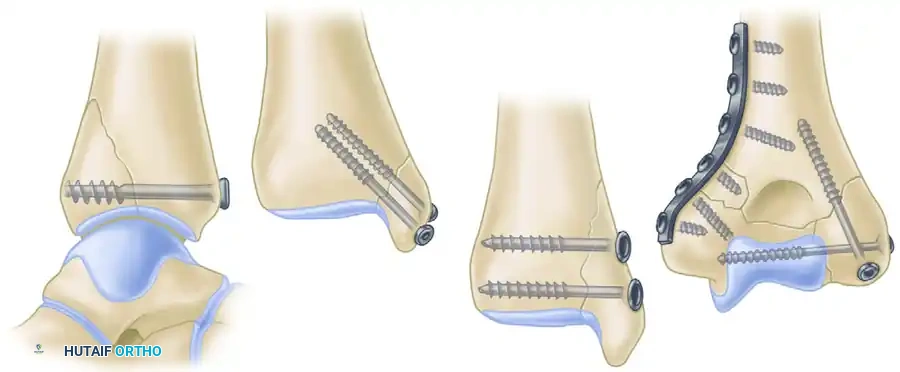
As illustrated in the provided surgical diagrams (Figure 53-25), intra-articular epiphyseal and metaphyseal fractures are routinely reconstructed with partially threaded lag screws:
- A. Posterior Lip Ankle Fracture (Posterior Malleolus): A large 6.4-mm partially threaded cancellous screw is utilized. The trajectory is typically anterior-to-posterior (or posterior-to-anterior depending on the approach), capturing the posterior fragment and compressing it against the tibial plafond to restore the articular surface.
- B & C. Medial Malleolar Fractures: Two 4.0-mm partially threaded small fragment cancellous bone screws are standard. Two screws are utilized to control rotational forces. They are directed perpendicular to the fracture plane (often vertically or slightly obliquely) to compress the medial malleolus back onto the tibial metaphysis.
- D. Distal Humerus Fractures: Two 4.0-mm partially threaded small fragment cancellous bone screws are used for lag screw fixation of the epiphysis (intercondylar split) and fixation of the condyle to the metaphysis. This restores the articular block before it is attached to the humeral shaft with neutralization plates.
Clinical Pearl: When using partially threaded cancellous screws, it is absolutely critical that all threads cross the fracture line. If even a single thread remains in the near fragment, the screw will act as a position screw, and no interfragmentary compression will be achieved. The fracture gap will remain held open.
Postoperative Protocol and Rehabilitation
The postoperative protocol following lag screw fixation depends heavily on the anatomical location, bone quality, and whether the lag screws were used in isolation or protected by a neutralization plate.
Immobilization and Weight-Bearing
- Isolated Lag Screws (e.g., Medial Malleolus): While lag screws provide absolute stability, they offer poor resistance to bending and torsional forces. Therefore, isolated lag screw fixation usually requires postoperative protection with a cast or rigid orthosis. Weight-bearing is typically restricted (non-weight-bearing or touch-down weight-bearing) for 4 to 6 weeks until radiographic evidence of primary bone healing is observed.
- Lag Screws with Neutralization Plates (e.g., Distal Humerus, Fibula): When a lag screw is protected by a neutralization plate, the construct is significantly stronger. Early active range of motion (ROM) is highly encouraged to prevent joint stiffness, particularly in the elbow and ankle. Weight-bearing restrictions still apply based on the specific fracture pattern, but joint mobilization can begin within days of surgery.
Radiographic Follow-up
Standard orthogonal radiographs should be obtained at 2 weeks, 6 weeks, and 12 weeks postoperatively. Because lag screw fixation promotes primary bone healing, surgeons should not expect to see abundant bridging callus. Instead, successful healing is indicated by the gradual disappearance (obliteration) of the fracture line.
Complications and Troubleshooting
- Loss of Reduction: Usually caused by failing to drill perpendicular to the fracture plane, failing to countersink (causing the near cortex to shift), or removing provisional K-wires too early.
- Thermal Necrosis: Drilling dense cortical bone generates significant heat. Failure to use saline irrigation during drilling can lead to thermal necrosis of the bone, resulting in premature screw loosening and loss of fixation.
- Hardware Prominence: In areas with minimal soft tissue coverage (e.g., the medial malleolus), prominent screw heads can cause painful bursitis or skin breakdown. Proper countersinking and selecting the correct screw length mitigate this risk.
- Stripping of the Far Cortex: Overtightening the screw, particularly in osteoporotic bone, can strip the threads in the far cortex. If this occurs, the lag effect is entirely lost. The surgeon must salvage the fixation by using a longer screw to engage the opposite cortex (if applicable), using a larger diameter rescue screw, or augmenting the fixation with a plate.
Conclusion
Lag screw fixation is an elegant, biomechanically sound technique that forms the cornerstone of modern fracture management. By strictly adhering to the principles of anatomical reduction, precise trajectory planning, meticulous hole preparation, and controlled compression, the orthopedic surgeon can achieve rigid absolute stability. This facilitates primary bone healing, allows for early rehabilitation, and ultimately restores optimal function to the traumatized limb. Mastery of this technique is non-negotiable for any practicing orthopedic surgeon.
You Might Also Like