Mastering Paley's Mechanical Axis Planning for Orthopedic Deformity Correction
Key Takeaway
Paley mechanical axis planning is a systematic, objective approach for orthopedic deformity correction. It involves rigorous geometric and trigonometric analysis of lower extremity radiographs, focusing on precise measurement of joint orientation angles and mechanical axis deviation to guide osteotomies and restore flawless limb alignment.
Introduction to Deformity Correction and Biomechanics
In the realm of orthopedic surgery, the transition from visually estimating a crooked leg to executing a mathematically flawless deformity correction is what separates a competent technician from a master surgeon. The foundation of this mastery lies in frontal plane mechanical axis planning, a systematic, highly objective approach pioneered by Dr. Dror Paley. Before the standardization of Paley deformity correction principles, osteotomies were often fraught with unintended secondary translations, joint line obliquities, premature joint degeneration, and unpredictable limb lengths. The era of "eyeballing" an osteotomy has been entirely replaced by rigorous geometric and trigonometric analysis.
This exhaustive masterclass is designed for orthopedic surgeons, deformity correction fellows, and residents who wish to deeply understand the geometry and biomechanics of the lower extremity. We will dissect the fundamental steps of mechanical axis planning, specifically focusing on tibial deformities, multi-level malalignments, and the intricate, unforgiving relationship between the femur and the tibia.
By mastering the Malalignment Test, the Proximal Mechanical Axis, the Distal Mechanical Axis, and the Center of Rotation of Angulation, you will be equipped to tackle the most complex lower limb deformities with absolute precision. Whether you are utilizing a medial opening wedge High Tibial Osteotomy, a Supramalleolar Osteotomy, an intramedullary nail, or a hexapod circular external fixator like the Taylor Spatial Frame, the preoperative mathematics remain exactly the same. The principles of Dr. Paley dictate that the biology of bone healing and the geometry of limb alignment are inextricably linked; you cannot optimize one while ignoring the other.
Radiographic Prerequisites for Accurate Planning
Before a surgeon can measure a single angle or draw a single line, they must ensure the imaging is flawless. The axiom "garbage in, garbage out" applies heavily to mechanical axis planning. A millimeter of rotational error on a radiograph can translate into degrees of angular error in the operating room.
Essential Imaging Protocols
To properly evaluate the frontal plane, you must obtain a 51-inch standing, weight-bearing anteroposterior radiograph of both lower extremities. This is non-negotiable.
- Patella Forward Positioning The radiograph must be taken with the patella facing strictly forward anteriorly, regardless of where the foot is pointing. If the patient has a rotational deformity and the foot is placed forward, the knee will be rotated. A rotated knee projects sagittal plane bowing into the frontal plane, creating a false deformity on the radiograph. This phenomenon is known as pseudovarus or pseudovalgus.
- Magnification Markers A spherical calibration marker, usually 25 millimeters in diameter, must be placed at the level of the bone being measured. This allows digital templating software to calculate exact lengths, translations, and hardware sizing. Placing the marker too anterior or posterior to the bone will result in magnification errors.
- Weight Bearing Status Supine films are entirely useless for mechanical axis planning. They eliminate the effect of gravity on joint laxity, ligamentous wear, and dynamic subluxation, effectively masking the true functional deformity. The limb must be loaded to reveal the actual mechanical axis deviation.
- Beam Centering The x-ray beam should be centered at the knee joint to minimize parallax distortion. If the beam is centered too high or too low, the joint space will appear artificially narrowed or distorted, making accurate joint orientation angle measurements impossible.
Surgical Pearls for Radiographic Assessment
* Always check the fibular head on the AP radiograph. If the fibular head is excessively overlapped by the tibia, the limb is externally rotated. If the fibular head is completely free of the tibia, the limb is internally rotated.
* If the patient has a significant Leg Length Discrepancy, place blocks under the short leg until the pelvis is level before taking the radiograph. This ensures the mechanical axis is evaluated in a functional stance.
The Orthopedic Lexicon of Angles and Axes
Before diving into the step-by-step planning, we must establish a rigorous understanding of the standard radiographic angles and axes. Orthopedic deformity correction has its own distinct language, and fluency in this lexicon is required for successful surgical execution.
The mechanical axis of the lower extremity is a line drawn from the center of the femoral head to the center of the ankle joint, which is the center of the tibial plafond. In a normal, well-aligned limb, this line passes just medial to the center of the knee joint, specifically through the medial tibial spine.
To plan a correction, we rely on joint orientation angles. These are the angles formed by the intersection of the mechanical or anatomic axes of the bones with the joint lines.
Key Normal Values in the Frontal Plane
A profound understanding of normal population parameters allows the surgeon to identify exactly where a deformity originates. The following values are the standard references used in Paley mechanical axis planning.
| Angle Abbreviation | Full Name | Normal Value | Acceptable Range | Clinical Significance |
|---|---|---|---|---|
| mLDFA | Mechanical Lateral Distal Femoral Angle | 87° | 85°–90° | Determines distal femoral varus/valgus. |
| MPTA | Medial Proximal Tibial Angle | 87° | 85°–90° | Determines proximal tibial varus/valgus. |
| LDTA | Lateral Distal Tibial Angle | 89° | 86°–92° | Determines distal tibial varus/valgus. |
| JLCA | Joint Line Convergence Angle | 0° to 2° | 0°–2° | Indicates intra-articular ligamentous laxity or cartilage loss. |
| LPFA | Lateral Proximal Femoral Angle | 90° | 85°–95° | Evaluates femoral neck shaft alignment relative to mechanical axis. |
Anatomic Versus Mechanical Axes
Understanding the distinction between anatomic and mechanical axes is critical, as confusing the two will lead to catastrophic surgical errors, particularly in the femur.
The Femur
The anatomic axis of the femur is a line drawn down the exact center of the medullary canal. The mechanical axis connects the center of the femoral head to the center of the knee. Because of the offset of the femoral neck and the natural bowing of the femur, these two lines are not the same. They diverge by approximately 7 degrees. This divergence is known as the Anatomic Mechanical Angle. When using intramedullary nails for femoral deformity correction, the surgeon must account for this 7-degree difference, as the nail will follow the anatomic axis, not the mechanical axis.
The Tibia
In the tibia, the mechanical axis and the anatomic axis are essentially parallel and superimposed. Therefore, drawing a line down the exact center of the tibial diaphysis represents both the mechanical and anatomic axis of that segment. This makes tibial planning uniquely straightforward compared to femoral planning. An intramedullary nail placed in the tibia will inherently restore the mechanical axis if the bone is straight.
The Paley Method for Mechanical Axis Planning
Dr. Paley’s methodology removes the guesswork from deformity correction. It is broken down into four distinct, sequential steps. You must never skip a step, as an error in the first step will compound into a disastrous surgical outcome by the final step.
Step Zero Performing the Malalignment Test
The Malalignment Test is your diagnostic baseline. It tells you if a deformity exists, but not necessarily where it is located. On the full-length, standing, weight-bearing AP radiograph, draw a line from the center of the femoral head to the center of the ankle joint.
This line represents the load-bearing axis of the limb. We measure the Mechanical Axis Deviation by looking at where this line passes through the knee joint. Normal Mechanical Axis Deviation is 0 to 8 millimeters medial to the exact center of the knee.
- Medial Mechanical Axis Deviation If the line passes significantly medial to the knee center, or falls completely inside the medial compartment, the patient has a varus deformity. This dramatically increases the contact stresses on the medial articular cartilage, leading to premature medial compartment osteoarthritis.
- Lateral Mechanical Axis Deviation If the line passes lateral to the center of the knee, the patient has a valgus deformity. This overloads the lateral compartment and places chronic tension on the medial collateral ligament.
If the Malalignment Test is abnormal, you must proceed to Step One to isolate the source of the deviation. The deviation could be arising from the femur, the tibia, the knee joint itself, or a combination of all three.
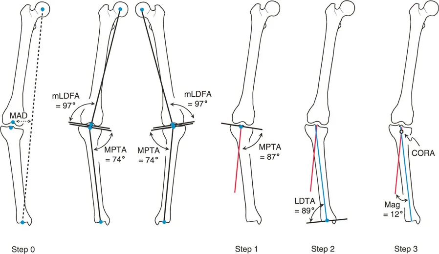
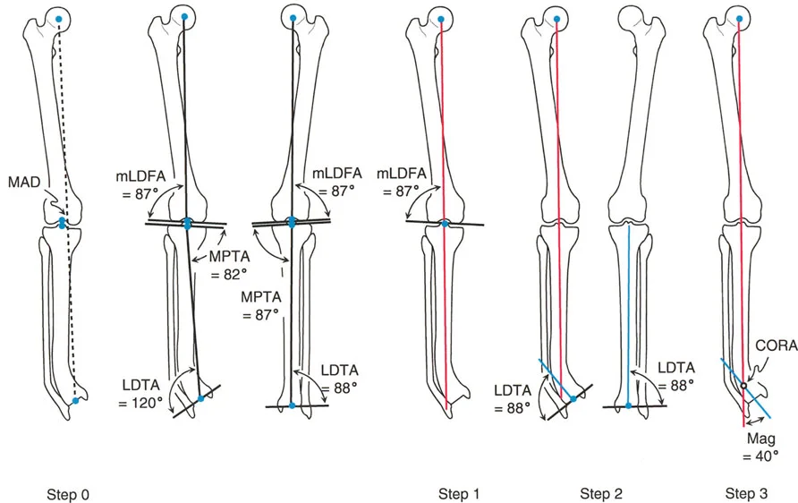
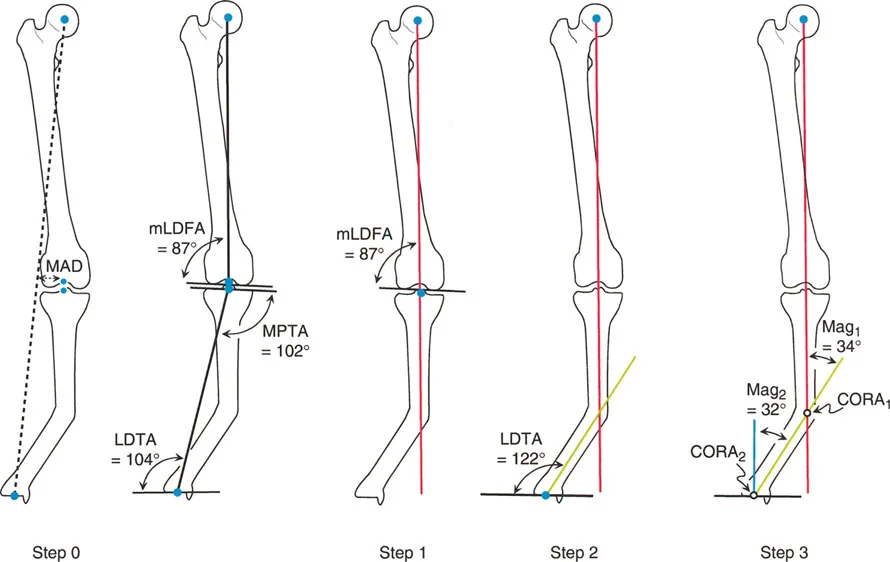
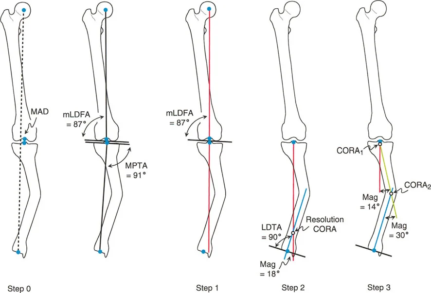
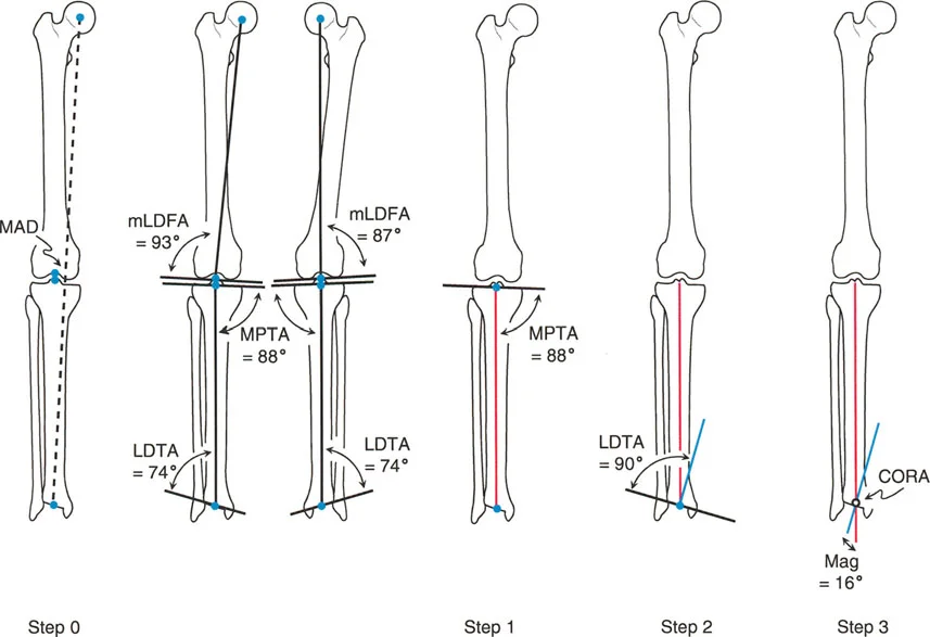
Step One Establishing the Proximal and Distal Mechanical Axes
Once you have confirmed an abnormal Mechanical Axis Deviation, you must evaluate the individual bones. We do this by drawing the Proximal Mechanical Axis and the Distal Mechanical Axis for the deformed bone. Let us assume we are evaluating a deformed tibia.
Drawing the Proximal Mechanical Axis
1. Draw the knee joint line across the proximal tibial articular surface.
2. Identify the normal Medial Proximal Tibial Angle, which is 87 degrees.
3. From the center of the proximal tibial joint line, draw a line distally at exactly 87 degrees to the joint line. This line represents where the mechanical axis should be if the proximal tibia were normal. This is your Proximal Mechanical Axis line.
Drawing the Distal Mechanical Axis
1. Draw the ankle joint line across the tibial plafond.
2. Identify the normal Lateral Distal Tibial Angle, which is 89 degrees.
3. From the center of the ankle joint, draw a line proximally at exactly 89 degrees to the joint line. This line represents where the mechanical axis should be if the distal tibia were normal. This is your Distal Mechanical Axis line.
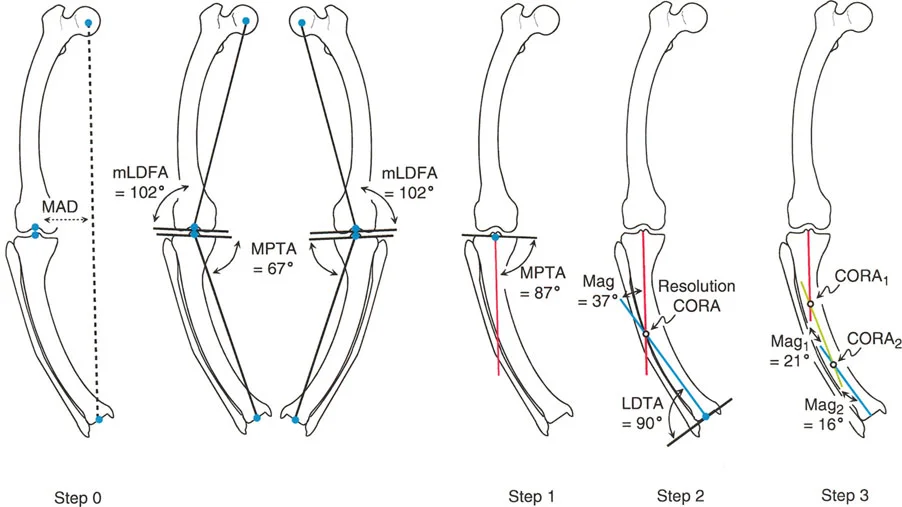
Step Two Locating the Center of Rotation of Angulation
The Center of Rotation of Angulation is the most critical concept in Paley deformity correction. The Center of Rotation of Angulation is defined mathematically as the exact point where the Proximal Mechanical Axis line and the Distal Mechanical Axis line intersect.
This intersection point represents the apex of the deformity. It tells the surgeon exactly where the bone is bent.
Clinical Implications of the Center of Rotation of Angulation
* Single Deformity If the Proximal and Distal lines intersect at a single point within the confines of the bone, the patient has a uniapical deformity.
* Multiple Deformities If the lines do not intersect at the obvious clinical apex, or if they run parallel to each other, the patient either has a multi-apical deformity or a pure translation deformity. In this case, a mid-diaphyseal line must be drawn to find the multiple intersection points.
* Magnitude of Deformity The angle formed by the intersection of the Proximal Mechanical Axis and Distal Mechanical Axis lines is the exact magnitude of the angular deformity. If the lines intersect at an angle of 15 degrees, you must perform a 15-degree correction.
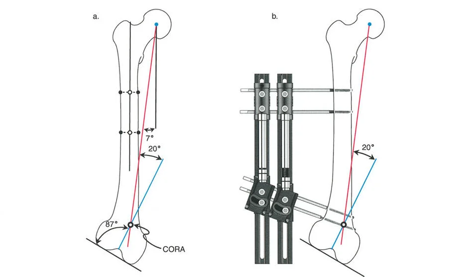
Step Three Applying the Paley Osteotomy Rules
Identifying the Center of Rotation of Angulation is only half the battle. The surgeon must now decide where to cut the bone the osteotomy and where to hinge the bone the Axis of Correction of Angulation. Dr. Paley established three unbreakable rules governing this relationship.
Osteotomy Rule One
When the osteotomy line and the Axis of Correction of Angulation both pass directly through the Center of Rotation of Angulation, the bone will undergo pure angulation with no translation. The mechanical axis will be perfectly restored.
* Clinical Application: This is the ideal scenario. An example is a supracondylar distal femoral osteotomy for a valgus deformity where the apex of the bend is exactly in the metaphyseal bone, allowing for excellent healing and simple plate fixation.
Osteotomy Rule Two
When the Axis of Correction of Angulation is placed at the Center of Rotation of Angulation, but the osteotomy cut is made at a different level, the bone will undergo angulation with an expected, calculated translation. The mechanical axis will still be perfectly restored.
* Clinical Application: This is incredibly common. If a patient has a sharp diaphyseal tibial bow, cutting the dense cortical bone at the exact Center of Rotation of Angulation might lead to non-union due to poor blood supply. Using Rule Two, the surgeon keeps the hinge at the diaphyseal apex but makes the actual bone cut in the proximal metaphyseal cancellous bone. The bone hinges around the apex, correcting the angle, but the bone ends at the cut site will translate. The surgeon must anticipate and accept this translation.
Osteotomy Rule Three
When neither the osteotomy cut nor the Axis of Correction of Angulation passes through the Center of Rotation of Angulation, the result is a translation deformity. The mechanical axis will remain deviated, and an iatrogenic malalignment is created.
* Clinical Application: This is a surgical failure. This frequently occurs when a surgeon places an intramedullary nail into a deformed bone without executing a translation at the osteotomy site. The bone ends are forced into alignment by the straight nail, but because the hinge was not at the apex, the entire distal segment shifts, resulting in a zigzag deformity.
Advanced Concepts in Deformity Correction
Mastering the basic uniapical tibial deformity is the first step. However, real-world orthopedic pathology rarely presents in such a pristine manner. Surgeons must be prepared to evaluate complex joint dynamics and multi-level structural failures.
Managing Joint Line Convergence Angle Pathologies
The Joint Line Convergence Angle represents the soft tissue component of a deformity. It is the angle formed between the distal femoral articular surface and the proximal tibial articular surface. In a perfectly stable knee, these lines are nearly parallel, creating a Joint Line Convergence Angle of 0 to 2 degrees.
When a patient has a severe, chronic varus deformity, the medial compartment cartilage wears away, and the lateral collateral ligament stretches out. This causes the joint to open up on the lateral side when the patient stands, resulting in a Joint Line Convergence Angle of perhaps 6 or 8 degrees.
The Danger of Ignoring Soft Tissue
If a surgeon plans a bony osteotomy based strictly on the mechanical axis lines but ignores a widened Joint Line Convergence Angle, the patient will be overcorrected or undercorrected when they stand up. The Paley method dictates that you must subtract the excess Joint Line Convergence Angle from your bony correction plan. If the patient has a 15-degree varus bony deformity, but 4 degrees of that varus is coming from joint laxity, you only perform an 11-degree bony osteotomy. Correcting the full 15 degrees in the bone would throw the patient into iatrogenic valgus once the ligaments take on weight.
Addressing Multi Level Malalignments
Frequently, patients present with deformities in both the femur and the tibia. A patient might have a valgus femur and a varus tibia. If the magnitudes are equal, the overall load-bearing axis might actually fall in the center of the knee, resulting in a normal Malalignment Test. This is known as a compensatory deformity. However, the joint line will be severely oblique, leading to shear forces that will rapidly destroy the knee cartilage.
Systematic Evaluation for Multi Level Disease
1. Perform the Malalignment Test. Even if normal, inspect the joint line obliquity.
2. Evaluate the femur independently. Draw the mechanical axis of the femur and measure the Mechanical Lateral Distal Femoral Angle. If it deviates from 87 degrees, a femoral osteotomy is required.
3. Evaluate the tibia independently. Draw the mechanical axis of the tibia and measure the Medial Proximal Tibial Angle. If it deviates from 87 degrees, a tibial osteotomy is required.
4. Plan two separate Centers of Rotation of Angulation. You must correct the femur to normal femoral parameters, and the tibia to normal tibial parameters. Attempting to correct a combined femur and tibia deformity with a single massive tibial cut will result in a disastrously oblique knee joint line.
Translating Preoperative Planning to Surgical Execution
The mathematical precision of the Paley method is only useful if it can be accurately translated to the operating room. The choice of fixation depends heavily on the osteotomy rules utilized and the quality of the host bone.
Fixation Strategies and Biomechanical Considerations
Internal Fixation with Plates and Screws
When utilizing Osteotomy Rule One pure angulation, locking plates provide excellent stability. Opening wedge osteotomies are preferred in the proximal tibia to avoid the peroneal nerve and preserve limb length. The preoperative plan dictates the exact size of the wedge to be opened. If the plan calls for a 12-degree correction, the surgeon opens the osteotomy until a 12-degree wedge fits perfectly, then applies the plate.
Intramedullary Nailing
Nails are load-sharing devices that are excellent for diaphyseal deformities. However, as noted in Osteotomy Rule Three, nails can easily create translation deformities if not managed correctly. To use a nail for a deformity correction, the surgeon must often use blocking screws, also known as Poller screws. These screws are placed strategically in the medullary canal to artificially narrow the pathway of the nail, forcing the nail to follow the mechanical axis rather than the anatomic axis, thereby preventing unwanted translation.
Hexapod Circular External Fixators
Devices like the Taylor Spatial Frame are the ultimate expression of the Paley principles. These frames consist of two rings connected by six variable-length struts. The surgeon inputs the exact radiographic parameters the Center of Rotation of Angulation location, the angular deformity, and the translation into a computer program. The program generates a daily schedule for the patient to turn the struts.
The beauty of the hexapod frame is that it allows the Axis of Correction of Angulation to be placed virtually anywhere in space. The surgeon can make the bone cut in a healthy metaphyseal region Osteotomy Rule Two, and the computer will automatically calculate the complex multi-planar strut adjustments required to swing the bone around the true Center of Rotation of Angulation, perfectly restoring the mechanical axis over a period of weeks.
Key Surgical Takeaways for Deformity Execution
* Never compromise on the preoperative radiographs. If the films are rotated, cancel the planning session and order new films.
* Always respect the soft tissues. A mathematically perfect bone cut will fail if the ligaments are ignored.
* Understand that translation is not an error if it is planned. Utilizing Osteotomy Rule Two to move a cut into better healing bone is a hallmark of advanced surgical planning.
* The mechanical axis is the ultimate arbiter of success. Regardless of the hardware used, the post-operative standing radiograph must show the load-bearing line passing precisely through the intended quadrant of the knee joint.
By internalizing these geometric principles and adhering strictly to the Paley methodology, the orthopedic surgeon transforms deformity correction from a stressful, unpredictable art into a highly reproducible, mathematically sound science.
!!! info "Academic Resource & Medical Review"
This academic resource was prepared and medically reviewed by Prof. Dr. Mohammed Hutaif, Consultant Orthopedic & Spine Surgeon. It is formulated specifically for medical students, orthopedic residents, and surgeons preparing for high-stakes board examinations (AAOS, FRCS Tr & Orth, Arab Board).
!!! warning "Disclaimer"
The surgical techniques, classifications, and clinical guidelines presented herein are for educational and academic review purposes only. They are not intended to replace institutional protocols or independent clinical judgment.
You Might Also Like