Mastering Dynamic Deformities: Advanced Lever Arm Biomechanics & Paley Principles
Key Takeaway
Dynamic deformities relate to joint position, muscle function, and skeletal lever arms during movement. Lever arm dysfunction alters biomechanical leverage. Orthopedic surgeons correct these using Paley Principles, including CORA, Mechanical Axis Deviation (MAD), and Joint Orientation Angles, for precise limb reconstruction.
The Paradigm Shift From Static to Dynamic Deformities
In the foundational study of orthopedic deformity correction, the primary focus of surgical trainees often rests heavily on static deformities of the lower limbs. These encompass fixed bone deformities, malunions, nonunions, and rigid joint contractures that are easily measured on a static radiograph. However, to truly master lower limb reconstruction, osteotomy planning, and complex joint arthroplasty, a surgeon must evolve their understanding to encompass the fluid, kinetic world of dynamic deformities.
Dynamic deformities are fundamentally related to joint position in space, muscle function, and, most critically, the physical length and spatial orientation of skeletal lever arms during movement. If left untreated, dynamic deformities inevitably become static. This progression occurs either through the development of secondary structural deformities in the bone—dictated by Wolff's Law of bone remodeling under stress—or through the establishment of fixed, unyielding soft-tissue joint contractures.
Orthopedic surgeons must recognize that the musculoskeletal system is a complex mechanical linkage. Muscles act as biological motors, but they are entirely dependent on the skeletal system to act as a transmission. When the skeletal transmission is malaligned, the biological motors fail to produce effective motion, regardless of their intrinsic strength.
Understanding the Kinetic World of Lower Limb Reconstruction
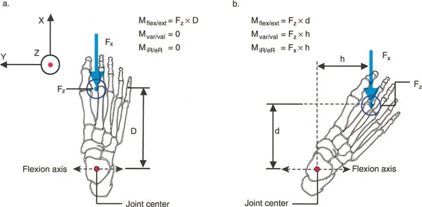
The transition from static analysis to dynamic understanding requires a paradigm shift in how we view radiographs and clinical examinations. A static radiograph only provides a snapshot of the skeletal transmission in a non-functional state. To understand the kinetic implications, the surgeon must visualize the ground reaction force (GRF) vector as it passes through the joints during the various phases of the gait cycle.
When a static deformity alters the position of a joint relative to the GRF vector, it creates an abnormal moment arm. This abnormal moment arm forces the surrounding musculature to work harder to maintain stability, leading to early fatigue, altered kinematics, and eventual joint degeneration. Correcting the static alignment is therefore not just an anatomical exercise; it is a profound functional restoration of the limb's kinetic capabilities.
Defining Lever Arm Dysfunction in Orthopedic Surgery
The term lever arm dysfunction was originally coined by Gage in 1991 to accurately describe the complex orthopedic deformities that arise in ambulatory children with cerebral palsy. However, its application extends far beyond pediatric neuro-orthopedics into the daily practice of trauma and adult reconstruction surgeons.
Orthopedic surgeons have historically been slow to recognize the paramount importance of lever arm dysfunction, often focusing solely on soft-tissue releases or tendon transfers. Surgical training frequently emphasizes thinking of muscles purely as biological power generators. However, it is a fundamental law of physics that power cannot be generated, transferred, or utilized without the benefit of the skeletal lever arms to which those muscles attach.
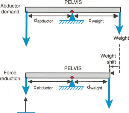
The Biomechanical Triad of Load Effort and Fulcrum
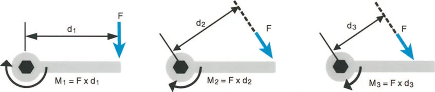
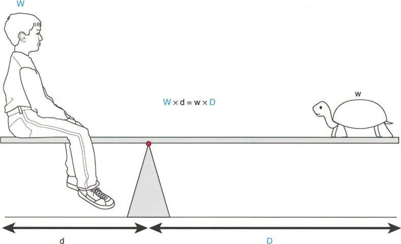
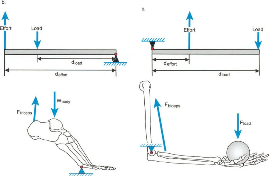
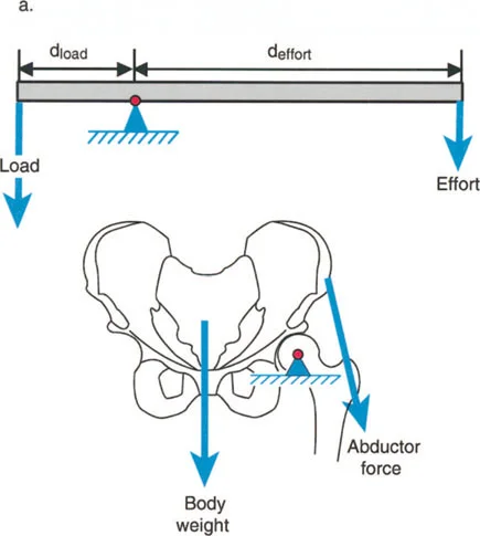
Lever arm dysfunction refers to the pathological alteration in the normal leverage relationships between three critical components of the biomechanical system.
- The Load The weight or resistance that must be overcome, which in the lower extremity is typically the body weight interacting with gravity and ground reaction forces.
- The Effort The muscular force applied to move or stabilize the load.
- The Fulcrum Position The joint around which rotation occurs, dictated by the articular geometry and surrounding ligamentous constraints.
Specifically, lever arm dysfunction describes a clinical condition in which internal and external lever arms become distorted due to bone malalignment, torsional deformities, or positional joint contractures. Once a surgeon begins to think in terms of moments generating power, rather than just isolated muscle contraction, they automatically begin to scrutinize the other half of the mechanical equation, which is the lever itself.
Clinical Manifestations of Lever Arm Pathology
While modern medicine can do very little to permanently increase the raw biological power generated by a muscle beyond physical therapy, the magnitude of the moment acting on a joint can often be dramatically increased simply by surgically correcting the lever arm dysfunction.
If a patient presents with a severe valgus deformity of the knee, the mechanical axis is shifted laterally. This increases the lever arm of the ground reaction force acting on the lateral compartment, leading to rapid cartilage wear. Simultaneously, the medial collateral ligament is subjected to chronic tensile overload. The muscles crossing the knee joint are now operating at a mechanical disadvantage, struggling to maintain coronal plane stability during the stance phase of gait.
Integrating Paley Principles to Correct Dynamic Deformities
To correct dynamic deformities and restore normal lever arm function, the surgeon must rely on a rigorous, systematic approach to static deformity analysis. The principles established by Dr. Dror Paley provide the ultimate framework for this process. By utilizing Paley's concepts of the Center of Rotation of Angulation (CORA), Mechanical Axis Deviation (MAD), and Joint Orientation Angles, surgeons can precisely quantify the skeletal malalignment that is driving the lever arm dysfunction.
Mechanical Axis Deviation MAD and Lever Arm Length
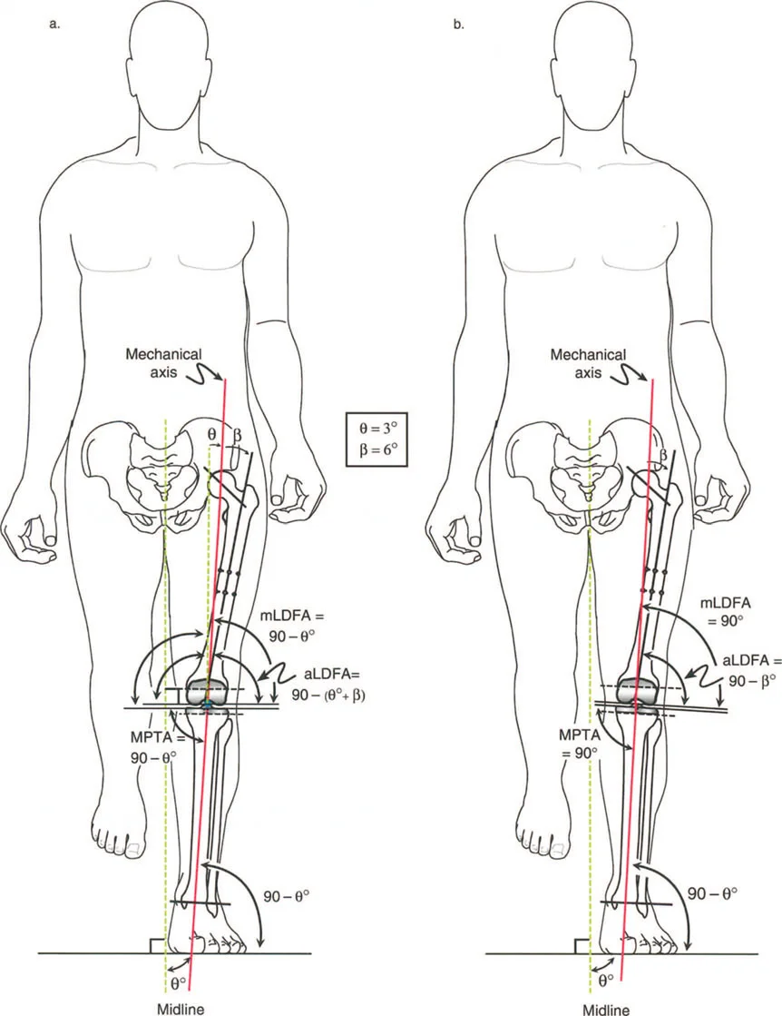
The Mechanical Axis Deviation (MAD) is the foundational measurement in lower limb deformity analysis. The mechanical axis of the lower extremity is defined by a line drawn from the center of the femoral head to the center of the ankle joint (the center of the tibial plafond). In a normally aligned limb, this line should pass slightly medial to the center of the knee joint.
When a deformity exists, the mechanical axis shifts away from the center of the knee. The distance from the center of the knee to the mechanical axis line is the MAD.
* A medial shift indicates a varus deformity, increasing the lever arm of the ground reaction force on the medial compartment.
* A lateral shift indicates a valgus deformity, increasing the lever arm on the lateral compartment.
By quantifying the MAD, the surgeon can directly measure the magnitude of the abnormal lever arm that is causing the dynamic dysfunction. Restoring the MAD to a normal physiological position is the primary goal of any lower limb realignment procedure.
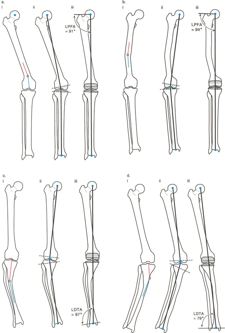
Joint Orientation Angles Restoring the Fulcrum
Once the MAD confirms the presence of a deformity, the surgeon must determine whether the pathology lies in the femur, the tibia, or within the joint space itself. This is achieved by measuring the Joint Orientation Angles. These angles define the relationship between the mechanical or anatomical axes of the bones and their respective joint lines.
To restore the fulcrum (the joint) to its proper spatial orientation, the surgeon must understand the normal physiological values for these angles.
| Joint Orientation Angle | Abbreviation | Normal Value Range | Clinical Significance |
|---|---|---|---|
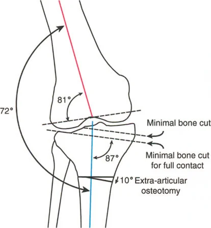
| Mechanical Lateral Distal Femoral Angle | mLDFA | 85 to 90 degrees | Determines distal femoral coronal alignment. |
| Mechanical Proximal Tibial Angle | MPTA | 85 to 90 degrees | Determines proximal tibial coronal alignment. |
| Joint Line Convergence Angle | JLCA | 0 to 2 degrees | Indicates intra-articular deformity or ligamentous laxity. |
| Mechanical Lateral Proximal Femoral Angle | mLPFA | 85 to 95 degrees | Assesses proximal femoral varus/valgus (Coxa Vara/Valga). |
| Posterior Proximal Tibial Angle | PPTA | 77 to 84 degrees | Determines tibial sagittal alignment (tibial slope). |
By comparing the patient's measured angles to these normative values, the surgeon can pinpoint the exact location of the structural deformity that is disrupting the lever arm. For instance, an abnormal mLDFA with a normal MPTA dictates that the corrective osteotomy must be performed on the femur to restore normal knee kinematics.
Center of Rotation of Angulation CORA
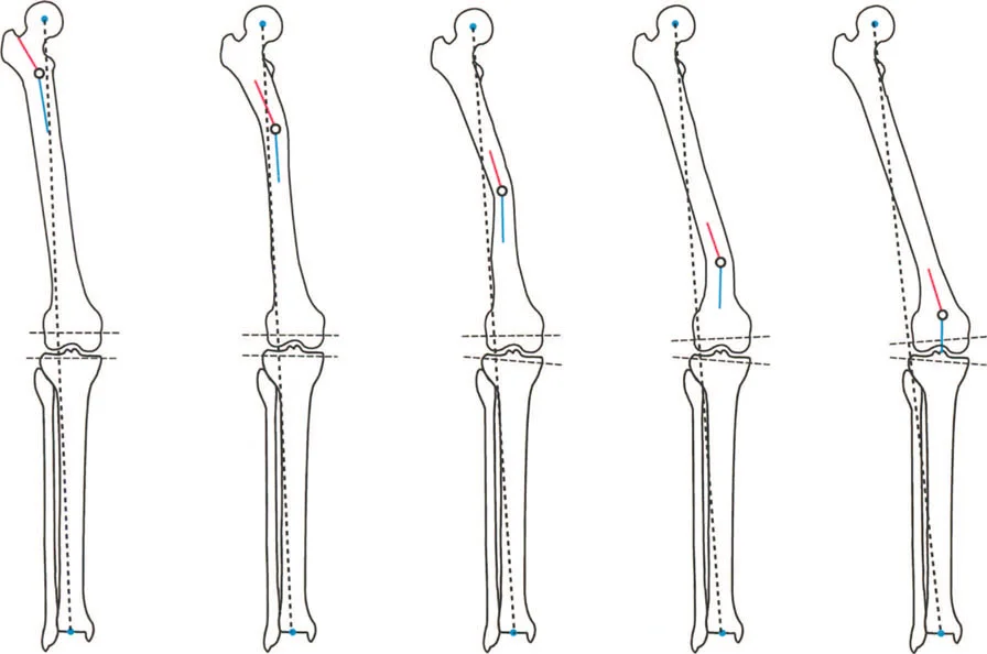
The Center of Rotation of Angulation (CORA) is perhaps the most critical concept in Paley's methodology. The CORA is the point at which the proximal and distal axes of a deformed bone intersect. It represents the apex of the deformity.
Finding the CORA is essential because it dictates where the corrective osteotomy should ideally be performed. If the lever arm of a muscle is shortened due to a diaphyseal bow in the femur, the CORA identifies the exact point of maximum angulation.
To find the CORA, the surgeon draws the mid-diaphyseal line of the proximal bone segment and the mid-diaphyseal line of the distal bone segment. The intersection of these two lines is the anatomical CORA. Alternatively, using mechanical axes, the intersection of the proximal mechanical axis and distal mechanical axis yields the mechanical CORA.
Paley Osteotomy Rules for Restoring Biomechanics
Identifying the CORA is only the first half of the surgical planning process. The surgeon must then decide where to make the bone cut (the osteotomy) and where to place the hinge (the axis of correction). Dr. Paley formulated three fundamental osteotomy rules that govern how a bone will behave when corrected. Mastering these rules is non-negotiable for surgeons attempting to restore complex lever arm biomechanics.
Rule One The Osteotomy and Hinge at the CORA
When the osteotomy and the hinge (the axis of rotation) are both placed exactly at the CORA, the bone segments will undergo pure angulation without any translation.
This is the most biomechanically sound and predictable method of correction. The proximal and distal mechanical axes will perfectly realign into a single straight line. In the context of lever arm restoration, Rule One ensures that the muscle origins and insertions are returned to their natural anatomical relationship without introducing secondary translational deformities that could alter muscle tension.
Rule Two The Osteotomy Separate from the CORA
In many clinical scenarios, it is not safe or practical to perform the osteotomy at the CORA. The CORA may be located within a joint space, in an area of poor soft-tissue coverage, or in a region of compromised bone quality.
Paley's Rule Two states that if the osteotomy is performed at a different level than the CORA, but the hinge remains at the CORA, the bone segments will undergo both angulation and translation. The mechanical axes will still perfectly realign, but the bone ends at the osteotomy site will be offset.
This translation is a necessary geometric consequence of rotating the bone around a distant point. Surgeons must anticipate this translation to ensure adequate bone contact for healing and to avoid tethering neurovascular structures.
Rule Three The Osteotomy Outside the CORA with Translation
Rule Three occurs when the osteotomy and the hinge are both placed away from the CORA.
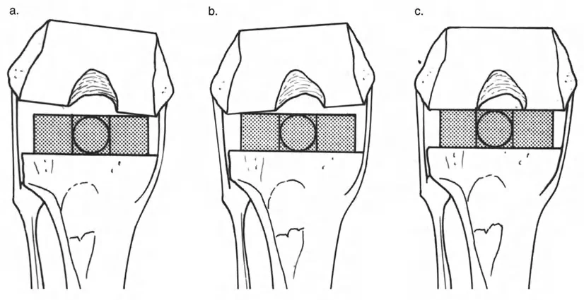
When the bone is angulated around this eccentric hinge, a new deformity is created. The mechanical axes will no longer align, resulting in a persistent translation deformity. This is generally an unintended consequence of poor preoperative planning.
However, Rule Three can occasionally be used intentionally. If a patient has a pre-existing translational deformity in addition to an angular deformity, the surgeon can strategically place the hinge away from the CORA to simultaneously correct both the angulation and the translation with a single osteotomy.
Step by Step Preoperative Planning for Lever Arm Restoration
Successful execution of a deformity correction requires meticulous preoperative planning. The surgeon must transition from the abstract concepts of MAD and CORA to a concrete surgical blueprint.
Step One Clinical and Radiographic Assessment
The process begins with a comprehensive clinical examination, assessing joint range of motion, muscle spasticity, and rotational profiles. Radiographic assessment is strictly standardized. The surgeon must obtain high-quality, full-length, weight-bearing anterior-posterior (AP) and lateral radiographs of both lower extremities. The patellae must be oriented strictly forward to eliminate rotational artifact when assessing coronal plane alignment.
Step Two Deformity Analysis and CORA Identification
Using digital templating software or traditional acetate overlays, the surgeon traces the mechanical and anatomical axes.
1. Draw the mechanical axis of the normal limb to establish a baseline.
2. Draw the mechanical axis of the deformed limb and calculate the Mechanical Axis Deviation (MAD).
3. Measure the Joint Orientation Angles (mLDFA, MPTA, JLCA) to localize the deformity to the femur, tibia, or joint.
4. Draw the proximal and distal axes of the deformed bone to locate the CORA.
Step Three Simulating the Correction
Once the CORA is identified, the surgeon simulates the osteotomy.
1. Choose the level of the osteotomy based on bone quality, soft tissue envelope, and fixation method.
2. Apply Paley's rules to determine the hinge placement.
3. Simulate the rotation of the distal segment until the mechanical axis is restored.
4. Measure the size of the resulting wedge (for opening or closing wedge osteotomies) or the amount of translation required.
5. Select the appropriate hardware (plates, intramedullary nails, or external fixators) to stabilize the construct.
Advanced Clinical Scenarios in Dynamic Deformity Correction
To fully grasp the impact of lever arm dysfunction, we must examine specific clinical scenarios where altered skeletal geometry directly sabotages muscle function.
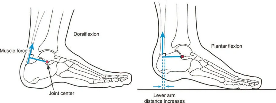
Functional Equinus and Sagittal Plane Lever Arms
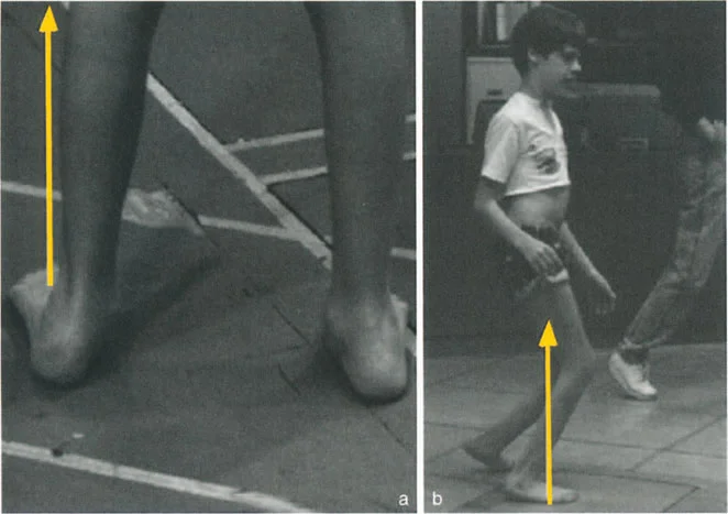
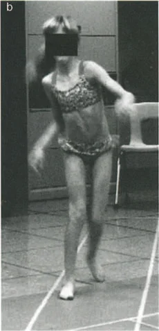
A classic clinical example of a dynamic deformity is functional equinus, frequently seen in cerebral palsy or post-traumatic spasticity. In a static clinical testing situation on the examination table, with the knee flexed to relax the gastrocnemius, the patient may possess the full capacity to passively dorsiflex the foot past neutral.
However, during the dynamic phase of single-leg stance in the gait cycle, the foot remains locked in a rigid equinus position. Why does this occur? Because the time required to apply upward muscular force and actively dorsiflex the foot is greater than the brief duration of the single-leg stance phase.
This is often exacerbated by underlying spasticity, where the stretch reflex of the Achilles tendon overpowers the anterior tibialis. The ground reaction force vector passes anterior to the knee and ankle, creating a massive extension moment at the knee and a plantarflexion moment at the ankle. The lever arm of the Achilles is functionally shortened relative to the demands of the gait cycle.
Severe Femoral Anteversion and Torsional Malalignment
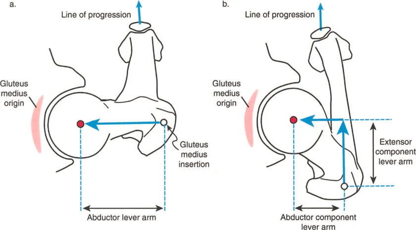
Other prime examples of dynamic deformities include severe femoral anteversion and tibial torsion. In these architectural anomalies, the physical length of the abductor muscle lever arm is pathologically shortened due to the bone deformity itself.
The gluteus medius muscle belly may be entirely healthy, well-innervated, and capable of generating normal biological force, but it suffers from profound clinical dysfunction because its mechanical advantage has been stripped away by the altered skeletal geometry.
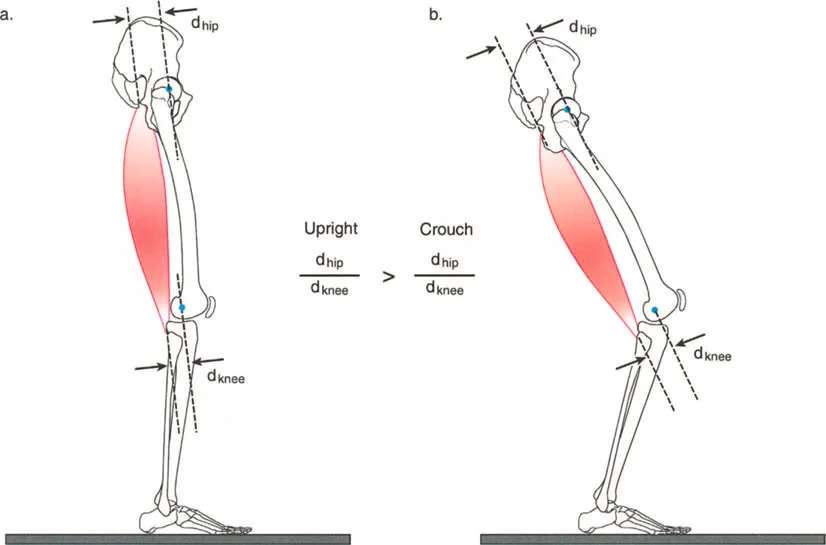
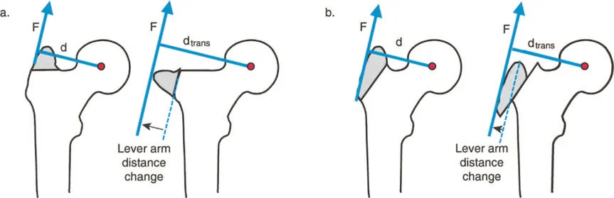
When the femur is highly anteverted, the greater trochanter is rotated anteriorly. To keep the foot pointing forward during gait, the patient must internally rotate the entire limb. This anterior positioning of the trochanter reduces the effective moment arm of the abductors in the coronal plane, leading to a Trendelenburg gait. Correcting the torsion via a derotational osteotomy instantly restores the mechanical advantage of the hip abductors.
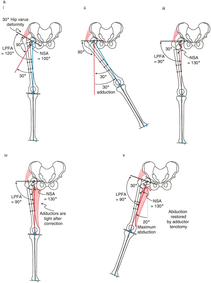
Coxa Vara and the Abductor Moment Arm
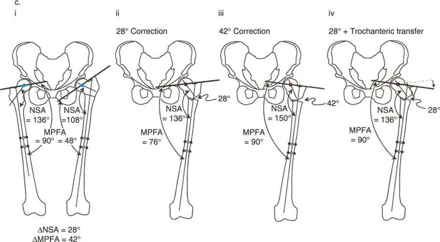
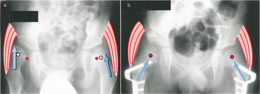
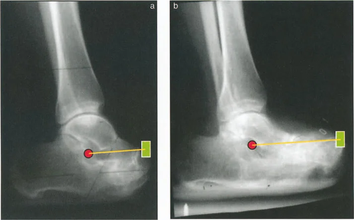
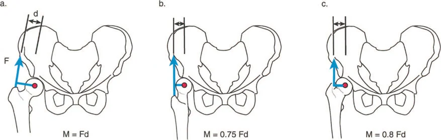
Coxa vara represents a severe disruption of the proximal femoral lever arm. In a normal hip, the neck-shaft angle is approximately 130 degrees, and the tip of the greater trochanter sits level with the center of the femoral head. This provides optimal tension and a long moment arm for the abductor musculature.
In coxa vara, the neck-shaft angle is decreased (often below 110 degrees). This drops the femoral head inferiorly relative to the greater trochanter, drastically shortening the articulotrochanteric distance (ATD). The abductors become slack, losing their resting tension, and their moment arm is physically shortened.
Applying Paley's principles, the surgeon identifies the proximal femoral CORA and performs a valgus-producing proximal femoral osteotomy. By increasing the neck-shaft angle, the surgeon distalizes the greater trochanter, restores the ATD, and instantly re-tensions the abductor lever arm, resolving the dynamic Trendelenburg lurch.
Modalities for Correcting Lever Arm Dysfunction
Once recognized and meticulously planned, lever arm dysfunction is generally straightforward to correct through biomechanical realignment. The surgeon must choose between acute correction with internal fixation or gradual correction using external fixation.
Acute Correction with Internal Fixation
Acute correction is ideal for single-plane deformities or isolated torsional malalignments where the soft tissue envelope can tolerate immediate stretching.
Torsional deformities like excessive femoral anteversion or tibial torsion are corrected with precise derotational osteotomies and stabilized with intramedullary nails or locking plates. This instantly restores the mechanical advantage of the hip abductors or the foot progression angle.
When performing acute corrections, the surgeon must be hyper-vigilant about neurovascular tension. Acute corrections of severe valgus knees, for example, can stretch the common peroneal nerve, leading to devastating foot drop. Prophylactic peroneal nerve decompression is often indicated in these scenarios.
Gradual Correction Using Tension Stress Principles
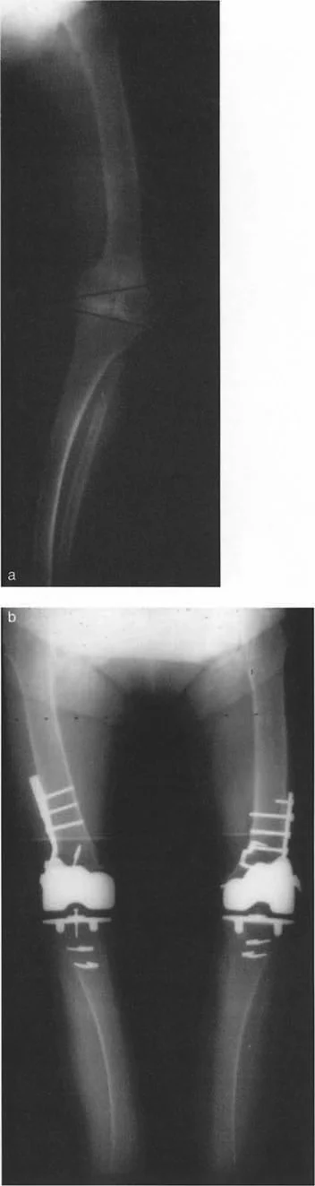
For multi-planar deformities, severe angulations, or cases complicated by leg length discrepancies (LLD) and nonunions, gradual correction is the gold standard.
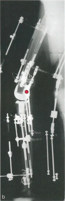
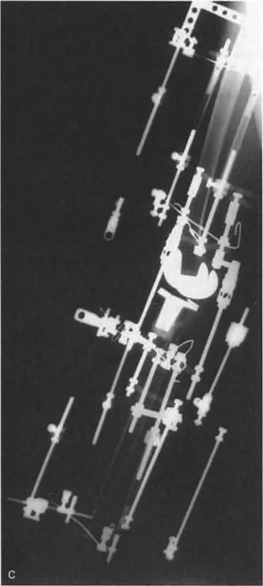
This approach utilizes the tension-stress principles introduced by Gavriil Ilizarov and De Bastiani. By applying a circular external fixator (such as the Ilizarov frame or the Taylor Spatial Frame), the surgeon performs a low-energy corticotomy.
Following a latency period, the frame is adjusted daily by the patient. This gradual distraction promotes distraction osteogenesis, allowing for the simultaneous correction of angulation, translation, rotation, and length.
Crucially, the gradual nature of the correction allows the soft tissues—nerves, vessels, and muscles—to safely adapt to their new lengths. As the skeletal lever arms are slowly restored to their anatomical positions, the biological motors are gradually re-tensioned, optimizing postoperative dynamic function.
Surgical Pearls for Mastering Deformity Correction
To execute these corrections flawlessly and master the interplay between static geometry and dynamic lever arms, consider the following high-yield surgical pearls:
- Respect the Soft Tissues Bone heals predictably; soft tissues do not. Always plan your surgical incisions and osteotomy levels to minimize periosteal stripping and preserve the vascular supply.
- The Patella is the Compass When obtaining full-length radiographs and when positioning the limb intraoperatively, the patella must be facing strictly forward. A rotated limb will create false varus or valgus measurements on a 2D radiograph.
- Joint Line Convergence Angle Matters Always measure the JLCA. If the JLCA is abnormal, correcting the bone alone will not
!!! info "Academic Resource & Medical Review"
This academic resource was prepared and medically reviewed by Prof. Dr. Mohammed Hutaif, Consultant Orthopedic & Spine Surgeon. It is formulated specifically for medical students, orthopedic residents, and surgeons preparing for high-stakes board examinations (AAOS, FRCS Tr & Orth, Arab Board).
!!! warning "Disclaimer"
The surgical techniques, classifications, and clinical guidelines presented herein are for educational and academic review purposes only. They are not intended to replace institutional protocols or independent clinical judgment.
You Might Also Like