Mastering Hip Deformity Correction: Paley Principles & Advanced Osteotomy Techniques
Key Takeaway
Hip deformity correction applies Paley principles like CORA, ACA, and Mechanical Axis Deviation to precisely plan osteotomies. This framework addresses complex multiplanar deformities, including SCFE and sagittal plane issues, in the proximal femur. The goal is anatomical restoration, preventing avascular necrosis and secondary osteoarthritis.
Introduction to Hip Joint Deformity Correction
For the orthopedic surgeon in training, the hip joint presents one of the most formidable biomechanical challenges in deformity correction. Unlike the knee or the tibia, where deformities often present clearly in orthogonal planes such as the coronal or sagittal plane, the proximal femur is a highly complex three dimensional structure. The femoral neck is inclined relative to the anatomical axis of the femoral shaft, meaning that any pathology affecting the femoral head or neck will inevitably create multiplanar oblique deformities.
This masterclass transforms the foundational Paley principles of deformity correction specifically focusing on the Center of Rotation of Angulation, the Axis of Correction of Angulation, and Mechanical Axis Deviation and applies them directly to the nuanced considerations of the hip joint. We will dissect sagittal plane deformities, decode the complex geometric paradoxes of Slipped Capital Femoral Epiphysis, and establish a bulletproof step by step framework for selecting the optimal osteotomy level. The ultimate goal is to balance perfect anatomical restoration against the dreaded catastrophic risk of Avascular Necrosis.
Core Paley Principles Applied to the Proximal Femur
To master hip deformity correction, the surgeon must abandon rudimentary visual estimation and adopt the rigorous mathematical framework pioneered by Dr Dror Paley. The proximal femur cannot be treated in isolation; its alignment dictates the biomechanical environment of the entire lower extremity.
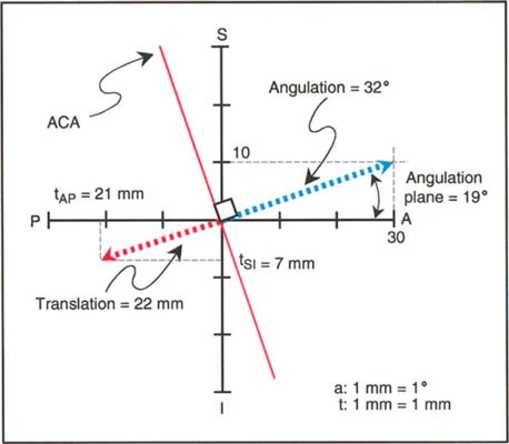
Understanding the Center of Rotation of Angulation
The Center of Rotation of Angulation represents the intersection of the proximal and distal mechanical or anatomical axes of a deformed bone. In the proximal femur, locating the Center of Rotation of Angulation is uniquely challenging due to the natural offset of the femoral head and the built in neck shaft angle.
When a deformity occurs, such as in a malunited intertrochanteric fracture or a developmental varus deformity, drawing the mechanical axis of the proximal segment requires identifying the center of the femoral head and projecting a line at the normal mechanical lateral proximal femoral angle. The intersection of this line with the mechanical axis of the distal femoral shaft identifies the exact apex of the deformity.
Mechanical Axis Deviation and the Hip
Mechanical Axis Deviation is the absolute distance between the mechanical axis of the lower extremity and the center of the knee joint. While Mechanical Axis Deviation is typically measured at the knee, its origins frequently lie in the hip.
A severe coxa vara deformity shifts the mechanical axis of the entire lower limb medially, creating a medial Mechanical Axis Deviation and overloading the medial compartment of the knee. Conversely, coxa valga shifts the axis laterally. Correcting the hip deformity is not merely about restoring proximal femoral anatomy; it is a mandatory intervention to prevent early onset osteoarthritis of the knee.
Joint Orientation Angles of the Lower Extremity
Precise preoperative planning requires a deep understanding of normal joint orientation angles. Below is a high yield summary of the critical angles utilized in Paley deformity planning for the proximal femur.
| Angle Acronym | Full Name | Normal Value Range | Clinical Significance |
|---|---|---|---|
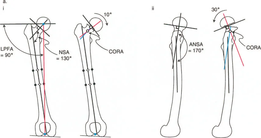
| mLPFA | Mechanical Lateral Proximal Femoral Angle | 85° to 95° (Mean 90°) | Defines the mechanical alignment of the proximal femur in the coronal plane. |
| aMPFA | Anatomical Medial Proximal Femoral Angle | 80° to 89° (Mean 84°) | Defines the anatomical neck shaft angle relationship. |
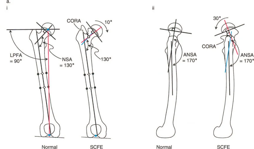
| NSA | Neck Shaft Angle | 124° to 136° (Mean 130°) | Critical for evaluating coxa vara or coxa valga. |
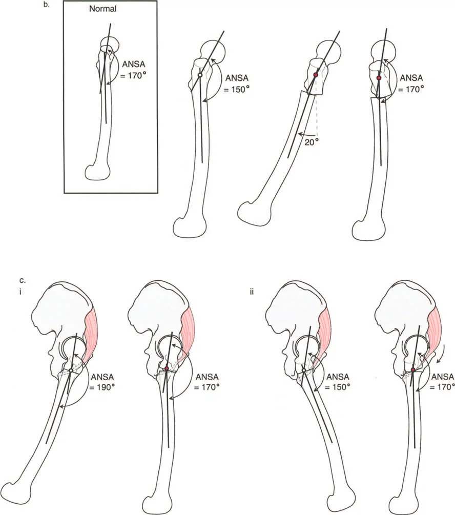
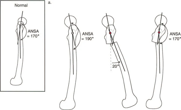
| ANSA | Anterior Neck Shaft Angle | 165° to 175° (Mean 170°) | Defines the sagittal plane relationship of the femoral neck. |
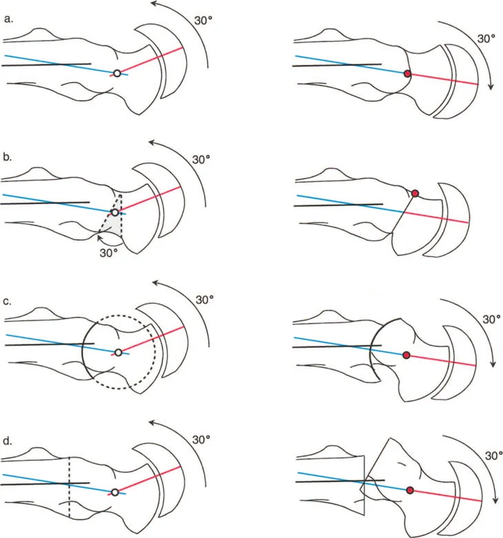
The Three Osteotomy Rules
Dr Paley established three fundamental rules of osteotomy that dictate the relationship between the osteotomy site, the Center of Rotation of Angulation, and the Axis of Correction of Angulation. Applying these to the hip is non negotiable for successful outcomes.
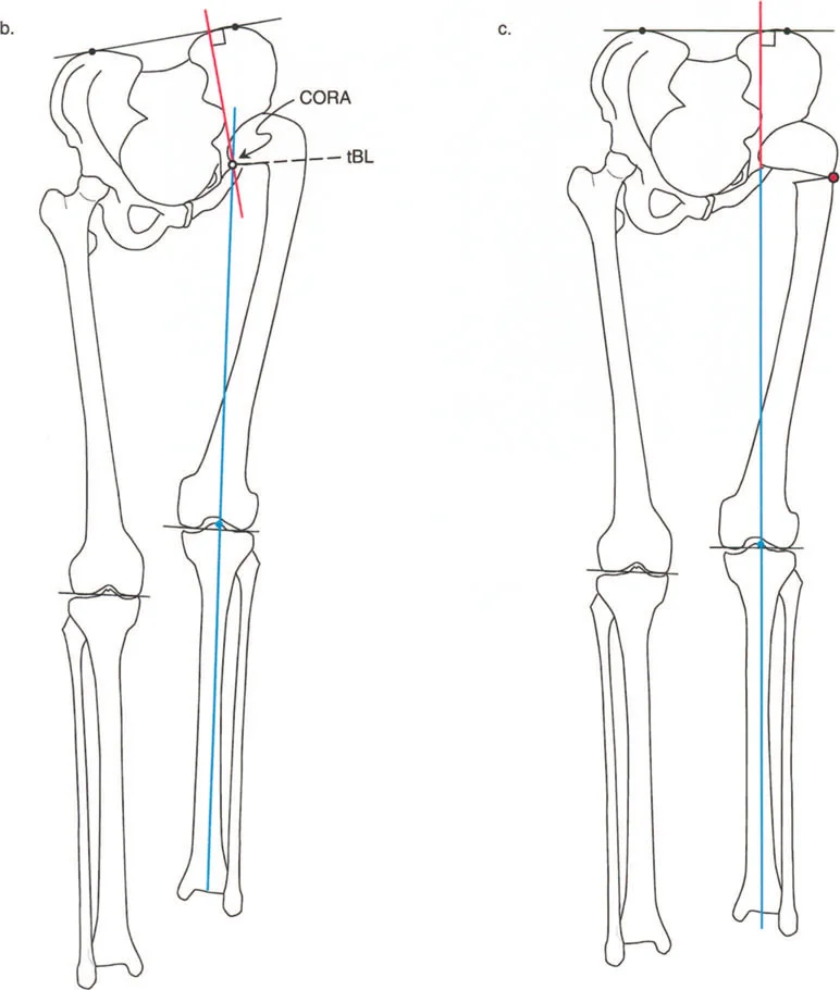
- Rule One: When the osteotomy and the Axis of Correction of Angulation are both located at the Center of Rotation of Angulation, pure angulation occurs without translation. The mechanical axis is fully restored.
- Rule Two: When the osteotomy is performed away from the Center of Rotation of Angulation, but the Axis of Correction of Angulation remains at the Center of Rotation of Angulation, the bone ends must translate to achieve mechanical axis realignment. In the proximal femur, this is often utilized in subtrochanteric osteotomies to correct neck shaft deformities, requiring intentional translation to restore the mechanical axis.
- Rule Three: When both the osteotomy and the Axis of Correction of Angulation are located away from the Center of Rotation of Angulation, a secondary translation deformity is created, leading to Mechanical Axis Deviation. This is a common pitfall in poorly planned hip surgeries.
Sagittal Plane Considerations of the Hip
When evaluating the hip, the frontal plane varus and valgus alignment often dominates the clinical picture and radiographic assessment. However, sagittal plane deformities involving flexion and extension are equally critical to joint longevity and patient function, though they are frequently masked by the innate compensatory mechanisms of the body.
Defining the Normal Anterior Neck Shaft Angle
To understand pathology, we must first rigorously define normal anatomy. In the sagittal plane, the normal Anterior Neck Shaft Angle of the proximal femur is 170°.
This slight anterior angulation is not a mere anatomical quirk; it is a critical component of normal hip biomechanics. The 170° Anterior Neck Shaft Angle allows for appropriate clearance of the anterior femoral neck against the acetabular rim during deep flexion, and it optimally tensions the anterior hip musculature, particularly the iliopsoas tendon.
When the Anterior Neck Shaft Angle deviates from this norm, we encounter structural flexion or extension deformities of the proximal femur, which drastically alter joint reactive forces and capsular tension.
Biomechanical Implications of Sagittal Deviation
A decrease in the Anterior Neck Shaft Angle represents a structural flexion deformity of the proximal femur. This anterior bend restricts hip extension. Conversely, an increase in the Anterior Neck Shaft Angle represents an extension deformity, restricting hip flexion. These structural bony blocks lead to early femoroacetabular impingement, labral tearing, and accelerated chondral wear.
Spinopelvic Compensatory Mechanisms
Flexion and extension deformities of the hip may originate from three primary sources including structural bone deformity originating in the pelvis or the proximal femur, soft tissue contractures such as severe psoas or rectus femoris tightness, and intra articular pathology limiting motion due to osteoarthritis or osteophytes.
A crucial clinical pearl for the reconstructive surgeon is that compensation for limitation of motion in the sagittal plane of the hip is almost entirely accomplished through the lower lumbar spine and pelvic tilt.
Fixed Flexion Deformities and Hyperlordosis
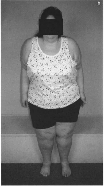
Fixed Flexion Deformities are compensated for by an anterior pelvic tilt and hyperlordosis of the lumbar spine. Because the hip cannot extend fully during the terminal stance phase of gait, the pelvis must tilt forward, forcing the lumbar spine into extreme extension to keep the trunk upright and the visual gaze horizontal.
Extension Deformities and Flat Back Syndrome
Extension deformities are compensated for by a posterior pelvic tilt and decreased lordosis, often referred to as flat back syndrome. The patient loses the natural shock absorbing curve of the lumbar spine, leading to rapid disc degeneration and sagittal imbalance.
Clinical Presentation and the Back Pain Connection
Because the spinopelvic complex is so adept at masking these limitations, most flexion and extension hip deformities remain asymptomatic at the hip joint itself in the early stages. Instead, the patient typically presents to the clinic complaining of chronic lower back pain due to the relentless postural strain on the lumbar facet joints and paraspinal muscles.
Fixed Flexion Deformity is a highly common associated finding with advanced osteoarthritis of the hip. When planning a valgus producing osteotomy for hip arthritis, incorporating an extension osteotomy component is often vital to correct the hidden Fixed Flexion Deformity and restore spinopelvic harmony.
Sagittal plane deformities of the acetabulum are notoriously difficult to reveal and diagnose on standard orthogonal radiographs. They are typically observed in association with systemic dysplasias, such as achondroplasia or severe developmental dysplasia of the hip.
Radiographic Evaluation and the Torsional Trap
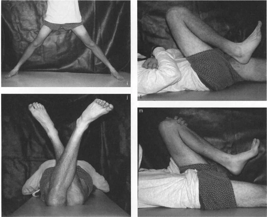
The most common cause of a sagittal plane hip deformity is a bony angulation in the proximal femur. However, before assuming the problem is a true flexion contracture or a structural sagittal bend, you must definitively rule out rotational torsional deformities.
Standard Radiographic Protocols for the Hip
Accurate deformity planning requires flawless imaging. A standard AP pelvis is insufficient for 3D deformity analysis. Surgeons must obtain a true AP view of the hip, a cross table lateral view, and full length standing leg radiographs to assess Mechanical Axis Deviation.
Decoding the Apparent Fixed Flexion Deformity
This is where standard radiography can deceive the untrained eye. To accurately assess the Anterior Neck Shaft Angle and the geometric configuration of the proximal femur, you must obtain a cross table lateral view radiograph oriented relative to the true AP view of the hip.
Here is the classic torsional trap. If there is a severe torsional deformity of the femur, such as excessive femoral anteversion, the true AP view of the knee with the patella facing forward will be vastly different from the true AP view of the hip. If the radiology technician obtains the cross table lateral view perpendicular to the true AP view of the knee rather than the hip, the anterior neck shaft angle may appear markedly flexed on the film. This creates an apparent Fixed Flexion Deformity of the hip, which is actually a rotational artifact masquerading as a sagittal deformity.
Step by Step Guide to Accurate Sagittal Imaging
To avoid the torsional trap, follow these specific imaging guidelines:
- Position the patient supine.
- Internally rotate the limb until the greater trochanter is maximally prominent laterally. This establishes the true AP of the proximal femur.
- Shoot the AP radiograph.
- Without changing the rotation of the limb, position the x ray beam horizontally at exactly 90 degrees to the AP beam to capture the cross table lateral.
- Evaluate the Anterior Neck Shaft Angle on this specific lateral projection.
The Diagnostic Rule dictates that a true Fixed Flexion Deformity due to structural angulation in the neck of the femur is only confirmed when the anterior neck shaft angle appears markedly flexed and the cross table lateral view of the hip corresponds perfectly to the true lateral view of the knee.
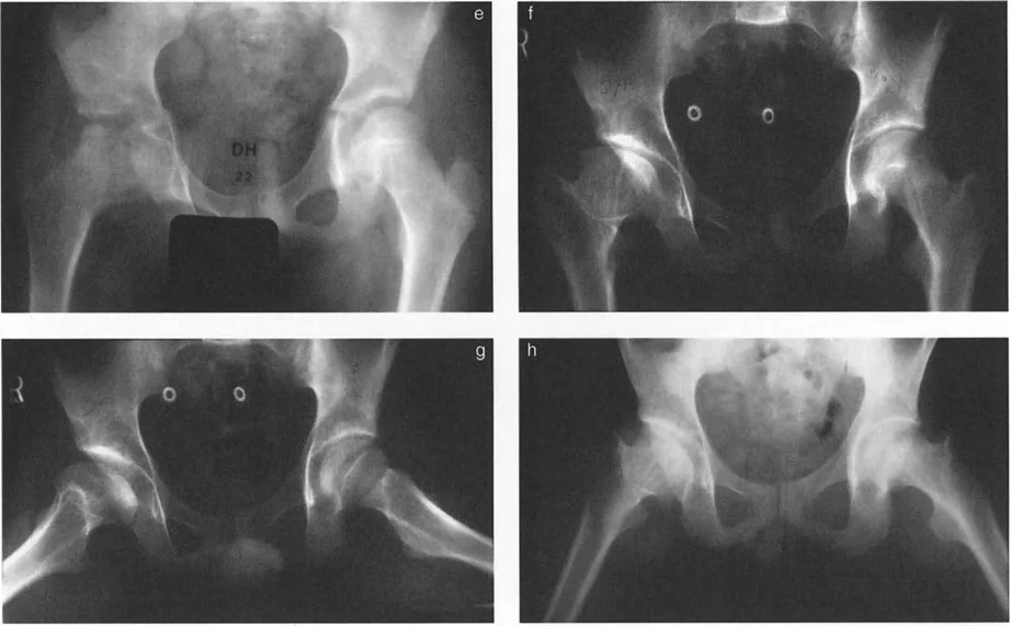
Slipped Capital Femoral Epiphysis and Geometric Paradoxes
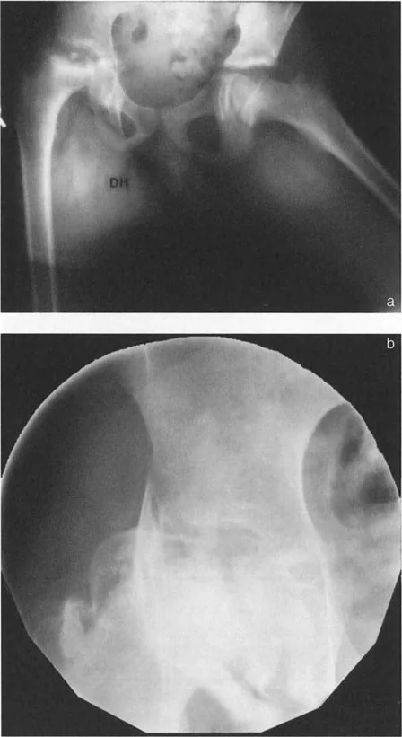
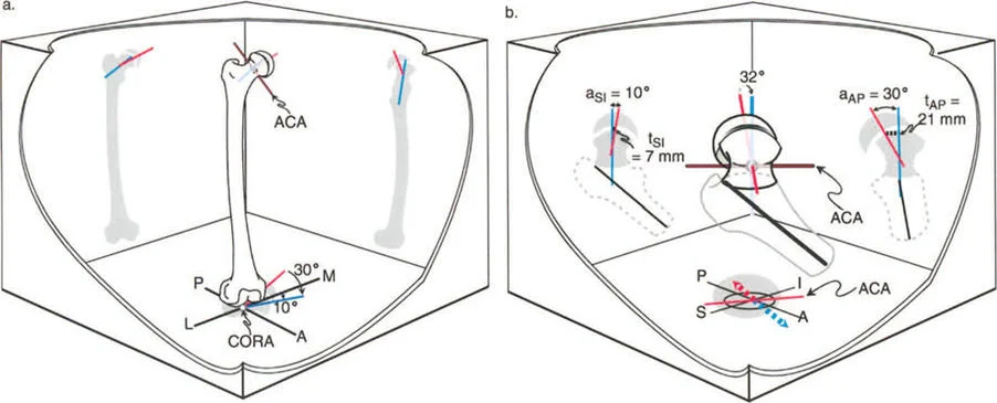
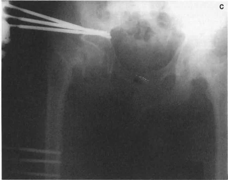
Slipped Capital Femoral Epiphysis represents one of the most complex multiplanar deformities encountered in orthopedic surgery. It is not merely a posterior slip; it is a three dimensional spatial translation and angulation of the epiphysis relative to the metaphysis.
Pathoanatomy of Slipped Capital Femoral Epiphysis
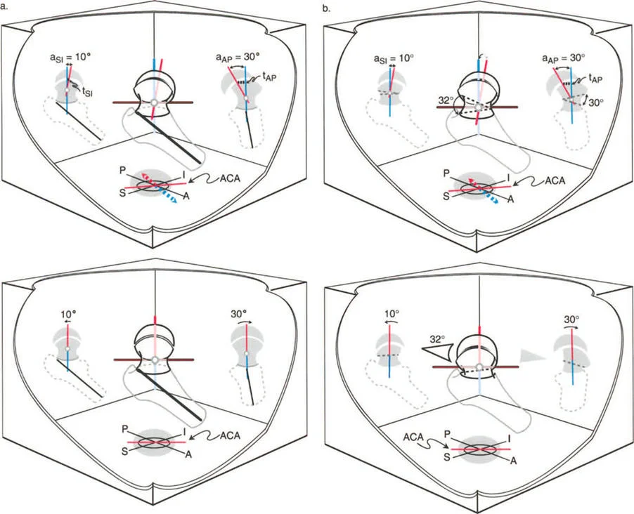
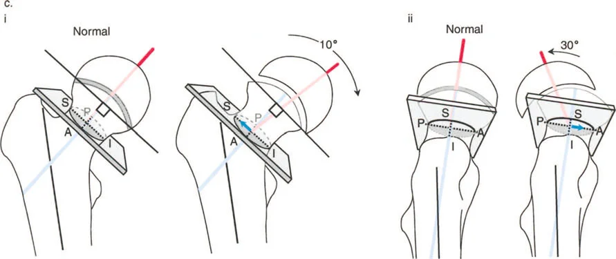
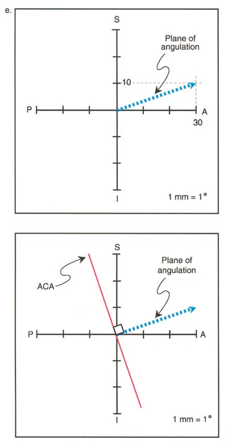
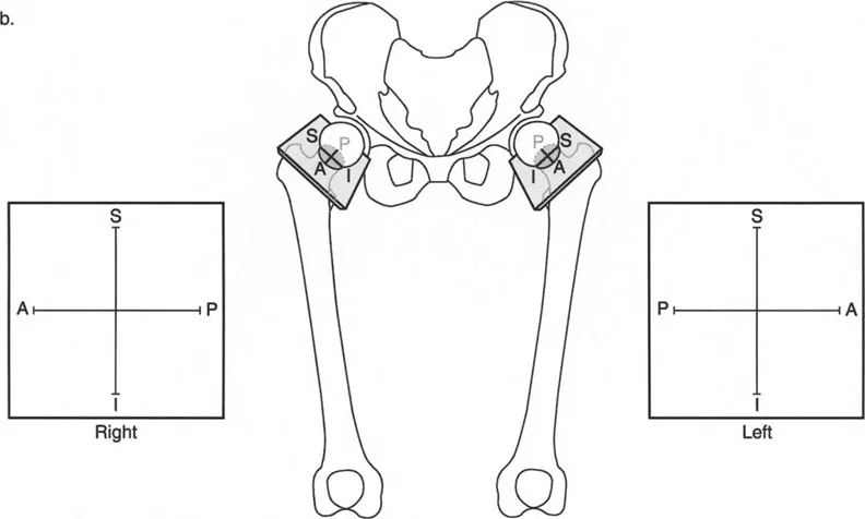
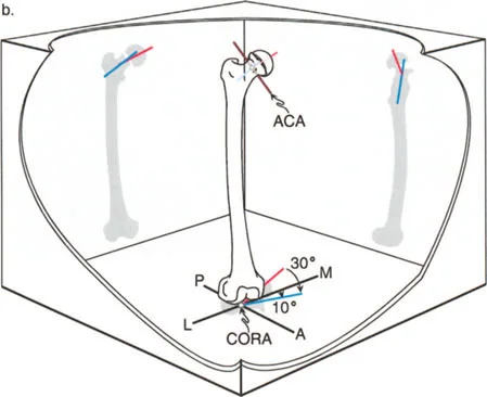
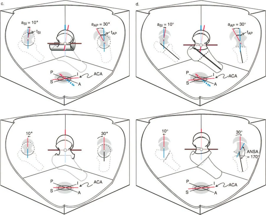
In Slipped Capital Femoral Epiphysis, the femoral neck displaces anteriorly, superiorly, and externally rotates relative to the capital femoral epiphysis, which remains anchored in the acetabulum. This creates a complex deformity characterized by coxa vara in the coronal plane, a severe extension deformity in the sagittal plane, and an external rotation deformity in the axial plane.
The Center of Rotation of Angulation for Slipped Capital Femoral Epiphysis is located precisely at the level of the physis. According to Paley Rule One, the most biomechanically sound correction would be an osteotomy at the physis itself.
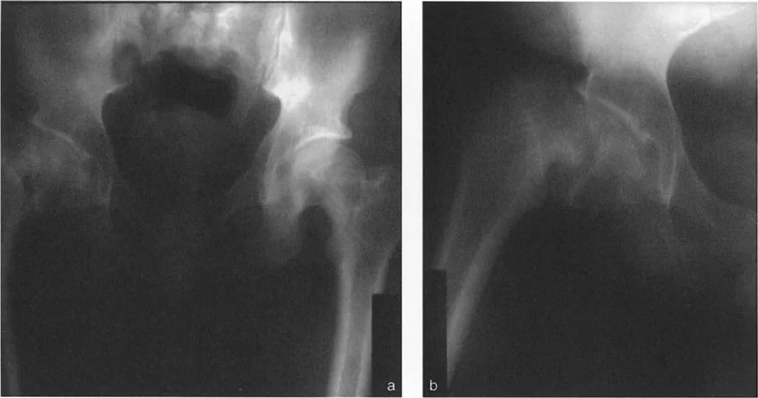
Three Dimensional Deformity Analysis in SCFE
Evaluating the magnitude of the slip requires assessing the Southwick angle on the lateral radiograph. The epiphyseal shaft angle is measured and compared to the contralateral normal side.
However, surgeons must recognize the geometric paradox of Slipped Capital Femoral Epiphysis. Because the deformity is oblique, orthogonal radiographs underestimate the true maximum deformity. The true apex of the deformity lies in an oblique plane situated between the coronal and sagittal planes. Preoperative planning must account for this oblique plane to ensure that a single stage multiplanar osteotomy corrects all components of the deformity simultaneously.
Balancing Anatomical Correction and Avascular Necrosis Risk
The ultimate goal in Slipped Capital Femoral Epiphysis reconstruction is to balance perfect anatomical restoration against the dreaded catastrophic risk of Avascular Necrosis.
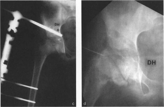
Performing a cuneiform osteotomy at the Center of Rotation of Angulation, such as the Dunn procedure, provides perfect anatomical restoration according to Paley Rule One. However, working at the intracapsular level of the femoral neck places the delicate medial circumflex femoral artery at extreme risk, carrying a high rate of Avascular Necrosis.
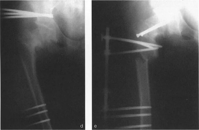
Alternatively, the Imhauser osteotomy is an extracapsular intertrochanteric osteotomy. Because the osteotomy is performed distal to the Center of Rotation of Angulation, it falls under Paley Rule Two or Rule Three. To prevent Mechanical Axis Deviation, the surgeon must induce a compensatory translation at the intertrochanteric level. While this does not perfectly restore the local anatomy of the femoral neck, it safely corrects the mechanical axis and joint orientation without risking the blood supply to the femoral head.
Preoperative Planning for Hip Osteotomies
Symptomatic bony deformities of the proximal femur that dictate surgical intervention require meticulous preoperative planning and precise intraoperative execution. The margin for error in the proximal femur is exceptionally narrow.
Step by Step Deformity Analysis
Mastering hip deformity correction requires a systematic approach to every radiograph.
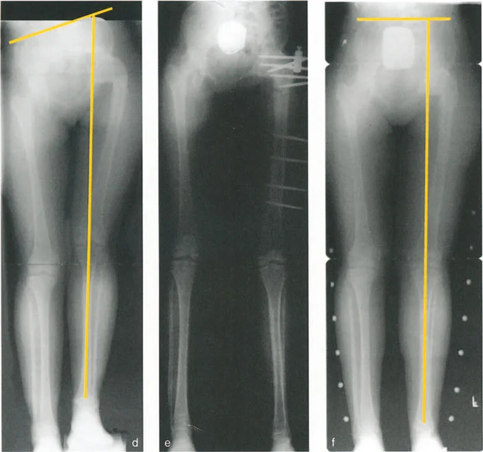
- Establish the Mechanical Axis: Draw the mechanical axis of the entire lower extremity on a standing AP radiograph to determine the Mechanical Axis Deviation.
- Determine Joint Orientation Angles: Measure the mLPFA and the aMPFA to quantify the coronal plane deformity.
- Locate the CORA: Draw the proximal and distal mechanical axes of the femur. Their intersection marks the Center of Rotation of Angulation.
- Assess the Sagittal Plane: Utilize the cross table lateral to measure the Anterior Neck Shaft Angle and identify structural flexion or extension deformities.
- Evaluate Torsion: Utilize CT scanograms to measure femoral anteversion and rule out rotational artifacts.
Selecting the Optimal Osteotomy Level
The selection of the osteotomy level depends on the location of the Center of Rotation of Angulation, the quality of the bone, and the planned fixation construct.
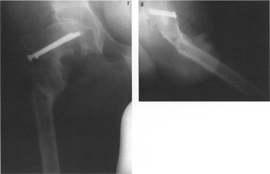
If the Center of Rotation of Angulation is in the femoral neck, an intertrochanteric osteotomy is typically preferred to avoid Avascular Necrosis, accepting the need for translation. If the Center of Rotation of Angulation is in the subtrochanteric region, a subtrochanteric osteotomy allows for Rule One correction, achieving pure angulation without translation.
Osteotomy Execution in the Sagittal and Coronal Planes
Once the planning is complete, the execution in the operating room demands absolute precision. The surgeon must control the proximal segment, which is notoriously difficult to manipulate due to the powerful pull of the abductors and the iliopsoas.
Intertrochanteric versus Subtrochanteric Osteotomies
Intertrochanteric osteotomies are highly versatile. They allow for massive multiplanar corrections, including varus, valgus, flexion, extension, and rotational adjustments. Because the intertrochanteric region is composed of highly vascular cancellous bone, the healing rates are exceptionally high.
Subtrochanteric osteotomies are utilized when the deformity extends into the diaphysis. This region consists of dense cortical bone, which heals slower and requires highly stable fixation to prevent nonunion.
Imbrication of the Osteotomy Rules for the Hip
When executing an intertrochanteric osteotomy for a femoral neck deformity, the surgeon is intentionally violating Rule One to preserve blood supply. By applying Rule Two, the surgeon creates a closing wedge or opening wedge osteotomy and translates the distal shaft medially or laterally.
For example, in a valgus producing osteotomy for coxa vara, the distal shaft must be translated medially. If this translation is not performed, the mechanical axis will be shifted laterally, creating a secondary valgus deformity at the knee.
Fixation Strategies and Biomechanical Stability
The choice of fixation is paramount. The proximal femur is subjected to massive bending moments, routinely experiencing forces several times body weight during normal gait.
- Fixed Angle Blade Plates: The gold standard for pediatric and young adult hip osteotomies. They provide absolute angular stability and allow the surgeon to build the correction directly into the seating of the blade.
- Dynamic Hip Screws: Useful for basic varus or valgus corrections but lack the multiplanar control of a blade plate.
- Cephalomedullary Nails: Excellent for subtrochanteric osteotomies, offering load sharing biomechanics and minimal soft tissue disruption.
- External Fixation: Utilized in complex cases requiring gradual correction, limb lengthening, or in the presence of active infection.
Conclusion and Future Directions in Hip Reconstruction
Mastering hip joint deformity correction requires a profound paradigm shift from intuitive visual surgery to rigorous mathematical planning. By applying the Paley principles of Center of Rotation of Angulation, Mechanical Axis Deviation, and the three osteotomy rules, the orthopedic surgeon can reliably deconstruct even the most complex multiplanar deformities.
Whether addressing the geometric paradoxes of Slipped Capital Femoral Epiphysis or deciphering the torsional traps of sagittal plane imaging, success hinges on meticulous preoperative analysis. As three dimensional modeling, patient specific instrumentation, and robotic assistance continue to evolve, the ability to execute these complex osteotomies will become more precise. However, the foundational biomechanical principles detailed in this masterclass will forever remain the bedrock of successful hip joint reconstruction and joint preservation.
!!! info "Academic Resource & Medical Review"
This academic resource was prepared and medically reviewed by Prof. Dr. Mohammed Hutaif, Consultant Orthopedic & Spine Surgeon. It is formulated specifically for medical students, orthopedic residents, and surgeons preparing for high-stakes board examinations (AAOS, FRCS Tr & Orth, Arab Board).
!!! warning "Disclaimer"
The surgical techniques, classifications, and clinical guidelines presented herein are for educational and academic review purposes only. They are not intended to replace institutional protocols or independent clinical judgment.
You Might Also Like