Mastering Orthopedic Deformity Correction: Advanced Osteotomy & Hardware
Key Takeaway
Orthopedic deformity correction employs Fixator Assisted Nailing and Paley Principles for precise alignment. The focal dome osteotomy, guided by drill guides at the Center of Rotation of Angulation, ensures optimal bone contact and stability. This restores the mechanical axis and normalizes joint orientation angles, crucial for successful outcomes.
Advanced Hardware and Osteotomy Considerations in Deformity Correction
The landscape of orthopedic deformity correction has evolved significantly over the past three decades. The field has transitioned from an era dominated by prolonged external fixation—often associated with pin tract infections, joint stiffness, and significant psychological burden on the patient—to advanced hybrid techniques that prioritize both anatomical precision and patient quality of life. Among these modern methodologies, Fixator Assisted Nailing stands out as a revolutionary paradigm in orthopedic surgery.
This advanced technique leverages the unparalleled multi-planar control of a temporary external fixator to acutely reduce and hold a complex deformity. Once the spatial alignment is perfected, an intramedullary nail is inserted for definitive, internal load-sharing fixation. The external frame is then removed in the same surgical setting. This masterclass delves into the intricate relationship between hardware selection, osteotomy geometry, and the fundamental biomechanics required to achieve flawless deformity correction. The success of these procedures relies entirely on the surgeon’s ability to manipulate bone segments around the Center of Rotation of Angulation without inducing secondary translation, unless purposefully planned.
Preoperative Planning Based on Paley Principles
Before any hardware touches the bone, meticulous preoperative planning based on the principles established by Dr. Dror Paley is absolutely mandatory. The Paley method provides a reproducible, geometric, and biomechanical framework for analyzing and correcting deformities. The ultimate goal of correcting lower extremity deformities, such as severe bilateral varus deformities of the tibiae, is to restore the Mechanical Axis Deviation to neutral and normalize the joint orientation angles across the hip, knee, and ankle.
Calculating Mechanical Axis Deviation
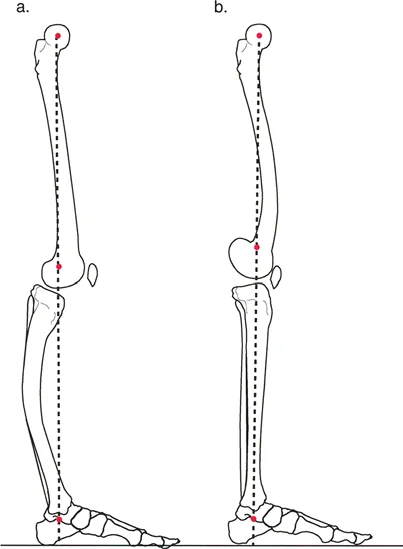
The Mechanical Axis Deviation is the foundational metric in lower limb deformity analysis. The mechanical axis of the lower extremity is defined by a line drawn from the center of the femoral head to the center of the tibial plafond. In a normal, well-aligned lower limb, this line should pass slightly medial to the exact center of the knee joint, typically 8 millimeters medial to the tibial spine.
When the mechanical axis falls outside of this normal zone, a Mechanical Axis Deviation is present.
* Medial Deviation Indicates a varus deformity, placing excessive compressive loads on the medial compartment of the knee and leading to premature osteoarthritis.
* Lateral Deviation Indicates a valgus deformity, overloading the lateral compartment and stretching the medial collateral ligamentous structures.
Quantifying the Mechanical Axis Deviation allows the surgeon to understand the magnitude of the global deformity. However, to correct it, the surgeon must identify the specific anatomical source of the deviation by analyzing the joint orientation angles.
Normalizing Joint Orientation Angles
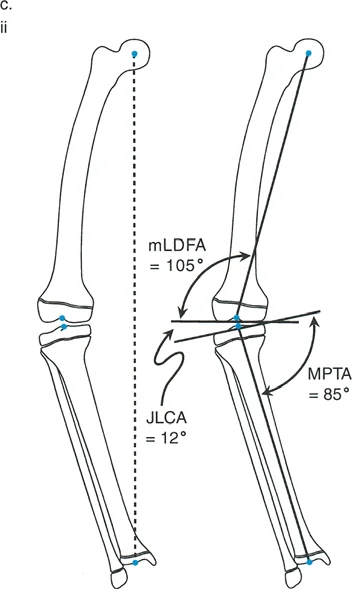
The Paley method relies on specific angular measurements to determine whether the deformity originates in the femur, the tibia, or both, and whether it is located in the proximal, diaphyseal, or distal segments. For the tibia, the primary angles of concern in the coronal plane are the Medial Proximal Tibial Angle and the Lateral Distal Tibial Angle.
To calculate these angles, the surgeon draws the mechanical axis of the individual bone (e.g., from the center of the knee to the center of the ankle for the tibia) and then draws the joint lines of the proximal and distal articular surfaces.
Standard Joint Orientation Angles
| Angle Designation | Anatomical Landmark | Normal Value Range | Clinical Significance |
|---|---|---|---|
| mLDFA | Mechanical Lateral Distal Femoral Angle | 85 to 90 degrees (Avg 88) | Determines distal femoral varus or valgus. |
| MPTA | Medial Proximal Tibial Angle | 85 to 90 degrees (Avg 87) | Determines proximal tibial varus or valgus. |
| LDTA | Lateral Distal Tibial Angle | 86 to 92 degrees (Avg 89) | Evaluates distal tibial articular alignment. |
| JLCA | Joint Line Convergence Angle | 0 to 2 degrees | Assesses intra-articular ligamentous laxity or cartilage loss. |
In a patient with a proximal tibial varus deformity, the Medial Proximal Tibial Angle will be significantly decreased (e.g., 75 degrees). The preoperative plan must calculate the exact degree of angular correction required to restore the Medial Proximal Tibial Angle to the anatomical norm of 87 degrees.
Identifying the Center of Rotation of Angulation
The Center of Rotation of Angulation is the most critical geometric concept in deformity correction. It is defined as the intersection of the proximal and distal mechanical (or anatomic) axes of a deformed bone. Identifying this intersection dictates exactly where the bone should be cut and how it should be rotated to achieve perfect alignment.
To find the Center of Rotation of Angulation, the surgeon draws the mid-diaphyseal line of the proximal bone segment and the mid-diaphyseal line of the distal bone segment on a true anteroposterior radiograph. The point where these two lines intersect is the Center of Rotation of Angulation. The angle formed between these two lines represents the true magnitude of the deformity.
The Three Rules of Osteotomy
Dr. Paley established three fundamental rules of osteotomy that govern how bone segments behave when manipulated around the Center of Rotation of Angulation. Understanding these rules is essential for preventing iatrogenic translation or mechanical axis malalignment during surgery.
- Rule One of Osteotomy If the osteotomy passes directly through the Center of Rotation of Angulation, and the bone is angulated around an axis that also passes through the Center of Rotation of Angulation, the mechanical axis will completely realign without any translation of the bone ends. This is the ideal scenario for a focal dome osteotomy.
- Rule Two of Osteotomy If the osteotomy is performed at a level different from the Center of Rotation of Angulation (due to poor soft tissue envelopes or hardware constraints), but the bone is still angulated around the Center of Rotation of Angulation, the mechanical axis will realign perfectly. However, the bone ends at the osteotomy site will translate. This translation is expected and mathematically necessary to restore the global axis.
- Rule Three of Osteotomy If the osteotomy is performed at a level different from the Center of Rotation of Angulation, and the bone is angulated around an axis located at the osteotomy site rather than the Center of Rotation of Angulation, the proximal and distal mechanical axes will become parallel but will remain translated. This results in a persistent Mechanical Axis Deviation and is generally considered a surgical failure unless intentionally planned to correct a pre-existing translation.
The Focal Dome Osteotomy
The focal dome osteotomy is an advanced surgical technique characterized by a cylindrical or semi-spherical cut made in the bone. Unlike a simple transverse osteotomy, which offers no inherent stability, or a closing wedge osteotomy, which invariably shortens the limb, the focal dome provides unparalleled biomechanical advantages for complex deformity correction.
In the context of proximal tibial varus correction, the focal dome osteotomy is planned precisely at the Center of Rotation of Angulation, adhering strictly to Paley's Rule One.
Advantages of the Focal Dome Technique
The focal dome osteotomy is highly favored in Fixator Assisted Nailing for several biomechanical and biological reasons.
First, it maintains excellent bony contact across the osteotomy site regardless of the degree of angular correction. Because the cut is cylindrical, rotating the distal segment along the track of the dome does not create large structural voids. This massive surface area of cancellous bone contact promotes rapid osteogenesis and early clinical union.
Second, the focal dome allows for simultaneous correction of angulation and translation without altering the overall leg length. In a closing wedge osteotomy, bone stock is removed, leading to limb shortening. In an opening wedge osteotomy, a void is created that often requires structural bone grafting and significantly increases the risk of delayed union or non-union. The focal dome avoids both of these pitfalls, making it the gold standard for metaphyseal deformity correction.
Biomechanics of Drill Guides in Osteotomy Execution
To achieve a perfect dome shape, the surgeon cannot simply use a freehand saw. Instead, multiple drill holes are made in a precise circular pattern around the Center of Rotation of Angulation.
The process begins by inserting a reference half-pin directly into the Center of Rotation of Angulation, perfectly perpendicular to the frontal plane of the bone under fluoroscopic guidance. This pin acts as the central axis—the fulcrum—around which the focal dome drill hole guide pivots. The radius of the drill guide dictates the size of the cylindrical cut.
Constrained Versus Unconstrained Drill Guides
The orthopedic market offers two primary types of drill guides used to create this circular pattern. Selecting the correct guide depends on the anatomical location of the osteotomy and the specific geometry of the patient's bone.
Constrained Drill Guides
This type of guide securely holds the drill bit within a rigid sleeve, physically preventing the bit from slipping or altering its trajectory. It is particularly useful for drilling the critical "edge holes" on the highly inclined, sloping cortical surfaces of the medial and lateral tibia. Because the drill bit is completely constrained by the metal sleeve, it cannot "walk" or slide down the slope of the bone. However, constrained guides are bulky and offer less flexibility when navigating tight soft tissue envelopes.
Unconstrained Drill Guides
An unconstrained guide provides the trajectory for the circular pattern but does not rigidly capture the drill bit. It acts more like a stencil. These guides are lower profile and highly adaptable to complex bone contours, but they present a significant technical challenge when drilling into sloped cortices.
Overcoming Sloping Cortices with Cannulated Systems
When using an unconstrained focal dome guide over the tibia, starting a hole on the sloping medial or lateral edges is notoriously difficult. A standard solid drill bit will simply slide off the hard cortical bone, destroying the periosteum and ruining the precise circular pattern required for a perfect dome.
High Yield Surgical Pearls for Unconstrained Guides
* Utilize K Wires First Instead of using a solid drill bit, the surgeon should first drive a sharp Kirschner wire (K-wire) through the unconstrained guide into the edge of the bone. The sharp point of the K-wire easily bites into the sloping cortex without slipping.
* Deploy Cannulated Drill Bits Once the K-wire is securely positioned in the cortex, a cannulated drill bit is passed over the wire. The K-wire acts as a monorail, completely eliminating drill walking and ensuring the hole is placed exactly on the planned circular arc.
* Maintain Soft Tissue Protection Always use drill sleeves to protect the saphenous nerve medially and the common peroneal nerve laterally when drilling the edge holes of the proximal tibia.
Table Comparison of Focal Dome Drill Guides
| Guide Characteristic | Constrained Drill Guide System | Unconstrained Drill Guide System |
|---|---|---|
| Drill Bit Slippage | Minimal to none due to rigid sleeves | High risk on sloping metaphyseal cortices |
| Ease of Use on Edges | High efficiency captures solid bits | Requires K-wire and cannulated bit technique |
| Intraoperative Flexibility | Rigid design makes it less adaptable | Highly adaptable to irregular bone contours |
| Speed of Execution | Faster for edge holes | Slower requires multi-step wire placement |
| Soft Tissue Profile | Bulky requires larger surgical exposure | Low profile requires minimal periosteal stripping |
Step by Step Execution of the Focal Dome Osteotomy
Once the drill guide has been used to pivot around the Center of Rotation of Angulation pin and a meticulous circular pattern of holes has been created, the bone is prepared for the final osteotomy. The execution of the cut must be performed with extreme care to prevent iatrogenic fractures from propagating into the articular joint surface.
Completing the Cortical Cut
The transition from a perforated bone to a fully mobile osteotomy requires precise osteotome technique.
- Connecting the Edge Holes An osteotome is introduced into the medial and lateral edge holes first. It is critical to cut the dense cortical edges before addressing the central cancellous bone. If the central bone is cut first, subsequent strikes on the hard cortical edges can cause a stress riser, leading to a catastrophic fissure fracture into the tibial plateau.
- Trans-secting the Posterior Cortex The posterior cortex of the tibia is carefully perforated using a curved osteotome. The surgeon must remain acutely aware of the popliteal artery and tibial nerve, which lie directly posterior to the surgical field.
- Completing the Dome Finally, the anterior and central cancellous bone bridges are divided. The surgeon then gently twists the osteotome to complete the osteoclasis. The proximal and distal segments should now be fully mobile, gliding smoothly along the cylindrical track of the focal dome.
Principles of Fixator Assisted Nailing
With the osteotomy complete and the bone segments mobile, the surgeon transitions to the Fixator Assisted Nailing phase. The objective is to use temporary external hardware to achieve anatomical reduction, followed by permanent internal hardware to maintain it.
Temporary External Fixation for Deformity Reduction
Schanz pins are inserted into the proximal and distal bone segments. A critical preoperative consideration is the placement of these pins: they must be positioned peripherally enough so that they do not block the trajectory of the intramedullary reamer or the final intramedullary nail.
Once the pins are placed, a monolateral fixator or a simple circular frame is attached. The surgeon uses the mechanical advantage of the fixator to dial in the correction. The distal segment is rotated along the focal dome until the mechanical axis is perfectly restored. This is confirmed intraoperatively using a radiopaque alignment rod (the "grid" or "cable" technique) over the fluoroscopy monitor, ensuring the mechanical axis passes from the center of the femoral head, through the desired coordinate in the knee, to the center of the ankle.
Intramedullary Reaming and Nail Insertion
Once perfect alignment is achieved and locked into place by the external fixator, the intramedullary canal is prepared.
A guidewire is passed from the proximal entry portal, across the focal dome osteotomy, and into the distal metaphysis. Because the external fixator is rigidly holding the reduction, the surgeon can ream the canal without fear of losing the alignment. Sequential reaming is performed to generate autologous bone graft (which is deposited at the osteotomy site) and to widen the canal to accommodate a robust, load-sharing intramedullary nail.
The nail is then inserted over the guidewire. Once the nail is fully seated and proximally and distally interlocked with screws, the temporary external fixator is completely dismantled and removed from the patient.
The Critical Role of Blocking Screws
A major challenge in intramedullary nailing of metaphyseal deformities is the "bell-clapper effect." The metaphysis of the tibia is wide and cavernous, whereas the intramedullary nail is relatively narrow. When a nail is inserted into this wide space, it tends to slide along the path of least resistance, which can result in a loss of reduction and a recurrence of the angular deformity.
To counteract this, surgeons utilize interference screws, widely known as Poller screws or blocking screws.
Biomechanics of Poller Screws in Metaphyseal Deformity
Blocking screws function by artificially narrowing the medullary canal, forcing the intramedullary nail into the exact center of the epiphysis. They rely on the principle of three-point bending.
Key Principles for Blocking Screw Placement
* Concave Side Placement Blocking screws must always be placed on the concave side of the deformity. In a varus deformity (where the medial side is compressed and the lateral side is tensioned), the concave side is medial. Placing a screw medially forces the nail laterally, correcting the varus alignment.
* Proximity to the Osteotomy The screws should be placed as close to the osteotomy site as possible, within the wide metaphyseal segment, to provide maximum mechanical leverage against the nail.
* Anteroposterior vs Coronal Placement Depending on whether the deformity is in the coronal plane (varus or valgus) or the sagittal plane (procurvatum or recurvatum), blocking screws are placed in the anteroposterior or medial-lateral direction to guide the nail appropriately.
By strategically placing one or two blocking screws before passing the intramedullary reamer, the surgeon creates a custom, constrained track for the nail. When the nail is finally inserted, it abuts against the blocking screws, locking the metaphyseal bone into perfect anatomical alignment.
Postoperative Protocol and Rehabilitation
The combination of a focal dome osteotomy, fixator-assisted reduction, and locked intramedullary nailing provides immediate, rigid structural stability. This allows for an accelerated postoperative rehabilitation protocol compared to traditional external fixation methods.
Maximizing Bone Healing and Functional Recovery
Because the intramedullary nail is a load-sharing device, patients are typically allowed early, protected weight-bearing. The axial micro-motion permitted by the nail stimulates secondary bone healing and robust callus formation at the focal dome osteotomy site.
Physical therapy focuses heavily on immediate range of motion exercises for the knee and ankle to prevent arthrofibrosis. Radiographic follow-up is conducted at regular intervals to monitor the progression of the bony union and to confirm that the restored mechanical axis and joint orientation angles are perfectly maintained throughout the healing cascade. By adhering to Paley's principles and mastering the nuances of advanced hardware application, orthopedic surgeons can achieve reproducible, high-quality outcomes in even the most complex deformity corrections.
!!! info "Academic Resource & Medical Review"
This academic resource was prepared and medically reviewed by Prof. Dr. Mohammed Hutaif, Consultant Orthopedic & Spine Surgeon. It is formulated specifically for medical students, orthopedic residents, and surgeons preparing for high-stakes board examinations (AAOS, FRCS Tr & Orth, Arab Board).
!!! warning "Disclaimer"
The surgical techniques, classifications, and clinical guidelines presented herein are for educational and academic review purposes only. They are not intended to replace institutional protocols or independent clinical judgment.
You Might Also Like