Mastering Multiplanar Deformities: Paley Single-Cut Osteotomy
Key Takeaway
The Paley Single-Cut Osteotomy is an advanced technique correcting complex angulation and rotation deformities simultaneously. Using precise geometric principles, a single inclined osteotomy allows acute correction and immediate internal fixation, restoring mechanical axis alignment efficiently.
Introduction to Multiplanar Deformity Correction
Orthopedic deformity correction represents one of the most complex, three-dimensional puzzles in modern surgical practice. For orthopedic surgeons, residents, and fellows in training, mastering single-plane deformities involving pure angulation in either the frontal or sagittal plane is a fundamental and necessary milestone. However, the true test of a deformity surgeon's spatial reasoning and technical skill lies in the comprehensive management of multiplanar deformities. Specifically, the most challenging scenarios involve combined angulation and rotation deformities.
Historically, correcting a long bone that is simultaneously bowed and twisted required highly complex interventions. Surgeons traditionally relied on multi-apical osteotomies, staged corrections utilizing circular external fixation systems like the Ilizarov apparatus, or closing wedge resections. Unfortunately, wedge resections inherently sacrifice valuable bone length, decrease structural stability, and often create secondary translation.
The paradigm shifted dramatically with the principles pioneered by Dr. Dror Paley. By rigorously defining the geometric relationship between the Axis of Correction of Angulation and the rotational deformity, surgeons can now execute a single inclined osteotomy. This elegant, mathematically derived cut perfectly corrects both the angular and rotational deformities simultaneously, allowing for acute correction and immediate internal fixation.
This comprehensive masterclass transforms the dense, highly mathematical concepts of Paley's deformity principles into an actionable, high-yield clinical framework. We will explore the foundational biomechanics, the critical joint orientation angles, the trigonometric foundations of the single-cut technique, the famous Banana Analogy, and the step-by-step surgical execution required to master the single-cut rotation-angulation correction.
Core Biomechanical Principles of Deformity Planning
Before diving into the complex mathematics of inclined axes and multiplanar correction, orthopedic surgeons must establish a rock-solid foundation in standard Paley terminology. Every successful osteotomy, whether a simple high tibial osteotomy or a complex multiplanar femoral correction, relies on strictly respecting these core biomechanical principles.
Mechanical Axis Deviation
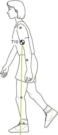
Mechanical Axis Deviation is the primary clinical and radiographic manifestation of lower extremity malalignment. It is measured on a standing, long-leg anteroposterior radiograph. The mechanical axis of the lower extremity is defined by a line drawn from the center of the femoral head to the center of the ankle joint (the tibial plafond).
In a normally aligned lower limb, this mechanical axis line passes slightly medial to the exact center of the knee joint, typically by about 8 millimeters. When a deformity is present, the mechanical axis deviates significantly.
* A mechanical axis passing excessively medial to the knee center indicates a varus deformity.
* A mechanical axis passing lateral to the knee center indicates a valgus deformity.
Correcting the combined angulation-rotation deformity aims to restore the Mechanical Axis Deviation to neutral. This restoration is critical for ensuring optimal compartmental joint loading, mitigating abnormal shear forces, and preventing the premature onset of osteoarthritis.
Center of Rotation of Angulation
The Center of Rotation of Angulation is the cornerstone of Paley's deformity planning. It is defined as the exact point in two-dimensional space where the proximal anatomical axis and the distal anatomical axis of a deformed bone intersect.
Finding the Center of Rotation of Angulation is the first step in any deformity planning process. In a pure angular deformity, the osteotomy should ideally pass directly through this specific point. When the osteotomy and the hinge point coincide at the Center of Rotation of Angulation, the surgeon can correct the angular deformity without inducing any iatrogenic translation of the bone segments.
Axis of Correction of Angulation
While the Center of Rotation of Angulation is a point on a two-dimensional radiograph, the Axis of Correction of Angulation is a line in three-dimensional space. It represents the theoretical hinge around which the distal bone segment rotates to align perfectly with the proximal bone segment.
The orientation of the Axis of Correction of Angulation dictates the plane of correction
* In a pure frontal plane deformity such as pure varus or valgus, the axis lies entirely in the sagittal plane.
* In a pure sagittal plane deformity such as pure procurvatum or recurvatum, the axis lies entirely in the frontal plane.
* In a combined angulation-rotation deformity, the axis must be oriented obliquely in three-dimensional space to address both the angular and rotational planes simultaneously.
Paley Joint Orientation Angles
To accurately locate the Center of Rotation of Angulation and quantify the magnitude of the deformity, surgeons must utilize standardized joint orientation angles. These angles define the relationship between the anatomical or mechanical axes of the long bones and their respective joint lines.
Deviations from the normal normative data indicate the specific location and magnitude of the deformity, whether it is intra-articular, metaphyseal, or diaphyseal.
Standard Lower Extremity Angles
Understanding and memorizing these angles is non-negotiable for the deformity surgeon. They form the basis of the reverse planning method used to map out the single inclined osteotomy.
| Angle Abbreviation | Full Name | Normal Range | Mean Value |
|---|---|---|---|
| mLDFA | Mechanical Lateral Distal Femoral Angle | 85° - 90° | 87.5° |
| MPTA | Medial Proximal Tibial Angle | 85° - 90° | 87.5° |
| JLCA | Joint Line Convergence Angle | 0° - 2° | 1° |
| LPFA | Lateral Proximal Femoral Angle | 85° - 95° | 90° |
| LDTA | Lateral Distal Tibial Angle | 86° - 92° | 89° |
When planning a correction, the surgeon draws the normal joint orientation angle from the joint line to establish the desired mechanical axis. The intersection of this newly drawn axis with the existing deformed axis pinpoints the Center of Rotation of Angulation.
The Three Paley Osteotomy Rules
Dr. Paley established three fundamental rules of osteotomy that govern the relationship between the Center of Rotation of Angulation, the Axis of Correction of Angulation, and the actual bone cut. Mastering these rules is essential before attempting a single inclined osteotomy for multiplanar deformities.
Osteotomy Rule One
When the osteotomy line and the Axis of Correction of Angulation both pass directly through the Center of Rotation of Angulation, the bone fragments will angulate without any translation. This is the ideal scenario for maintaining the mechanical axis and ensuring maximum bone-to-bone contact at the osteotomy site. The resulting correction is pure and predictable.
Osteotomy Rule Two
When the Axis of Correction of Angulation passes through the Center of Rotation of Angulation, but the actual osteotomy cut is performed at a different level, the bone fragments will undergo both angulation and translation.
This rule is frequently utilized in clinical practice. For example, in a distal femoral deformity where the Center of Rotation of Angulation is located directly on the joint line, cutting through the joint is impossible. The surgeon must place the osteotomy proximally in the metaphysis while keeping the hinge at the joint line. This results in an intentional, calculated translation that keeps the overall mechanical axis perfectly aligned.
Osteotomy Rule Three
When the osteotomy and the Axis of Correction of Angulation are both located at a level separate from the Center of Rotation of Angulation, the correction will result in a new, iatrogenic translation deformity. The mechanical axis will be shifted parallel to its intended path. This rule highlights a common surgical error and must be avoided unless a specific, parallel translation of the mechanical axis is desired.
The Challenge of Combined Rotation and Angulation
When a rotational deformity in the transverse plane is superimposed on an angular deformity in either the frontal or sagittal plane, the spatial geometry of the bone changes dramatically. This is the crux of the multiplanar deformity challenge.
If a surgeon simply cuts the bone transversely and rotates it to correct the transverse plane twist, the existing angular deformity will be projected into a new, unpredictable plane. Conversely, if the surgeon only corrects the angulation using a standard wedge or dome osteotomy, the patient's limb will remain malrotated. Persistent malrotation leads to severe gait abnormalities, altered foot progression angles, and devastating patellofemoral tracking issues.
The elegant and definitive solution to this complex problem is the Single Inclined Osteotomy. By calculating a specific oblique plane for the saw cut, the surgeon can rotate the bone fragments around a mathematically derived inclined axis. As the bone rotates to correct the twist, the oblique angle of the cut simultaneously unbends the angulation.
To visualize this complex three-dimensional maneuver, Dr. Paley utilizes the highly effective Banana Analogy.
Visualizing the Deformity with the Banana Analogy
Imagine a standard banana. It has a natural, distinct curve which represents a pure angulation deformity. Now imagine that this same banana is also twisted along its long axis, representing a superimposed rotational deformity.
To correct this twisted banana, we must find the exact plane where a single, straight saw cut allows us to untwist the banana while simultaneously straightening its curve. The mathematics behind this cut are precise and reproducible.
The Varus and Internal Rotation Banana Model
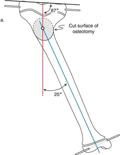
Let us break down a theoretical, highly exaggerated model for educational purposes. We have a right banana with a massive 45-degree varus deformity. We will define this angular deformity as Angle A, where A equals 45 degrees.
Simultaneously, this banana has a 25-degree internal rotation deformity. We will define this rotational deformity as Angle R, where R equals 25 degrees.
To simulate the knee and ankle joint axes in a classroom setting, we use simple toothpicks inserted into the ends of the banana. These toothpicks visually represent the 25-degree internal rotation deformity, much like internal tibial torsion seen in a clinical patient.
To execute the single-cut correction, we must calculate two critical geometric factors
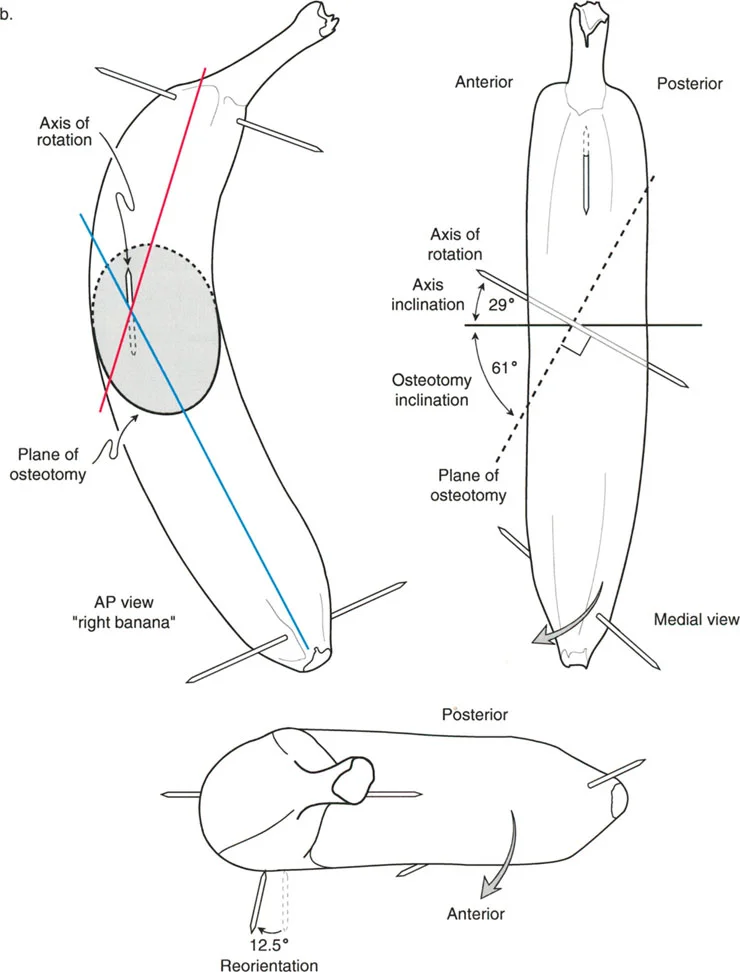
1. The Axis of Rotation This is the invisible line in three-dimensional space around which the distal bone segment will turn.
2. The Plane of the Osteotomy This is the actual physical path of the saw blade through the bone. By definition, the plane of the osteotomy is always exactly perpendicular to the axis of rotation.
Trigonometric Foundations of the Single Cut
Using trigonometric approximations, we can determine the exact angles required for this specific banana deformity. The formulas rely on the inverse tangent function applied to the ratio of the deformities.
-
Axis Inclination Calculation The inclination of the axis from the horizontal plane is calculated as the arctangent of the rotational deformity divided by the angular deformity.
Axis Inclination = arctan (R/A) = arctan (25°/45°) ≈ 29° -
Osteotomy Inclination Calculation The inclination of the actual saw cut from the horizontal plane is the arctangent of the angular deformity divided by the rotational deformity. Because the osteotomy is perpendicular to the axis, these two angles will always add up to 90 degrees.
Osteotomy Inclination = arctan (A/R) = arctan (45°/25°) ≈ 61°
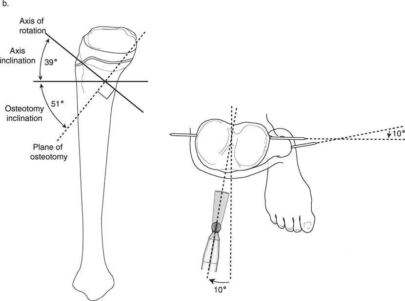
Figure 9-13b: The Reorientation Maneuver.
As seen in the illustration above, the inclined osteotomy is planned at 61° from the horizontal. The inclined axis about which this osteotomy rotates is perpendicular to the cut, meaning it is inclined 29° from the horizontal.
From the top bird-eye view, the surgeon must perform an initial reorientation maneuver, often referred to as the R/2 maneuver. The saw blade starts perpendicular to the proximal banana segment. It is then reoriented in the transverse plane by exactly 12.5 degrees, which is half of the 25-degree rotational deformity. Next, the saw is dropped down, inclining the blade upward by the calculated 61 degrees.
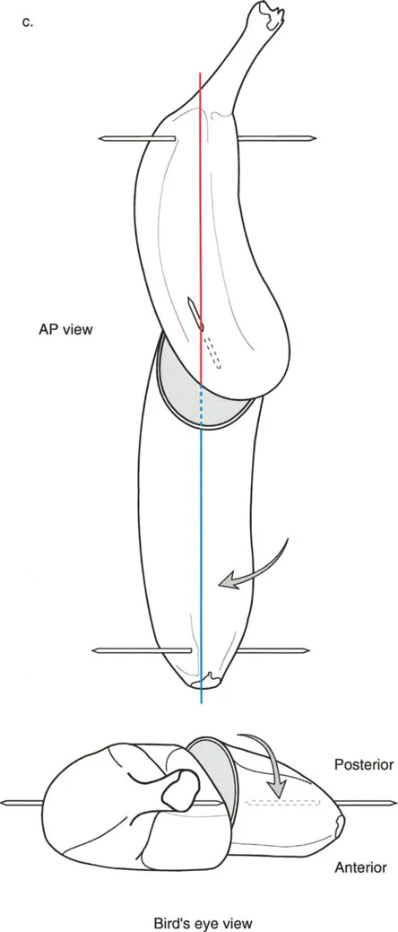
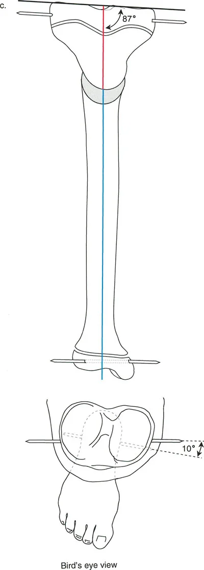
Figure 9-13c: The Corrected Banana.
After the completion of the osteotomy, the bone is rotated around the newly established axis. The magnitude of this rotation is a critical concept to grasp. The bone is not rotated just 25 degrees, nor is it rotated 45 degrees. The actual magnitude of rotation required is the hypotenuse of the two deformities.
Using the Pythagorean theorem for approximation, the true magnitude of rotation is approximately 51 degrees. Once rotated 51 degrees along this specific oblique plane, the banana is miraculously aligned in all planes. The 45-degree frontal angulation and the 25-degree transverse rotation are simultaneously neutralized.
Preoperative Planning for the Inclined Osteotomy
Executing a single inclined osteotomy in the operating room requires meticulous preoperative planning. The margin for error is incredibly small, as an improperly angled cut will exacerbate the multiplanar deformity rather than correct it.
Step One Obtaining Quality Imaging
The foundation of deformity correction is perfect imaging. Obtain full-length, weight-bearing anteroposterior and lateral radiographs of both lower extremities. Ensure the patella is facing straight forward to accurately assess the frontal plane. Obtain a CT scan to precisely quantify the transverse plane rotational deformity by superimposing the proximal and distal joint axes.
Step Two Identifying the Deformity Parameters
Calculate the Mechanical Axis Deviation and measure all relevant joint orientation angles (mLDFA, MPTA). Identify the Center of Rotation of Angulation on both the AP and lateral radiographs. Quantify the angular deformity (Angle A) and the rotational deformity (Angle R).
Step Three Calculating the Osteotomy Inclination
Utilize the arctangent formulas discussed in the banana analogy. Determine the precise angle of the osteotomy relative to the transverse plane. Calculate the R/2 value to determine the starting orientation of the saw blade.
Step Four Choosing the Fixation Method
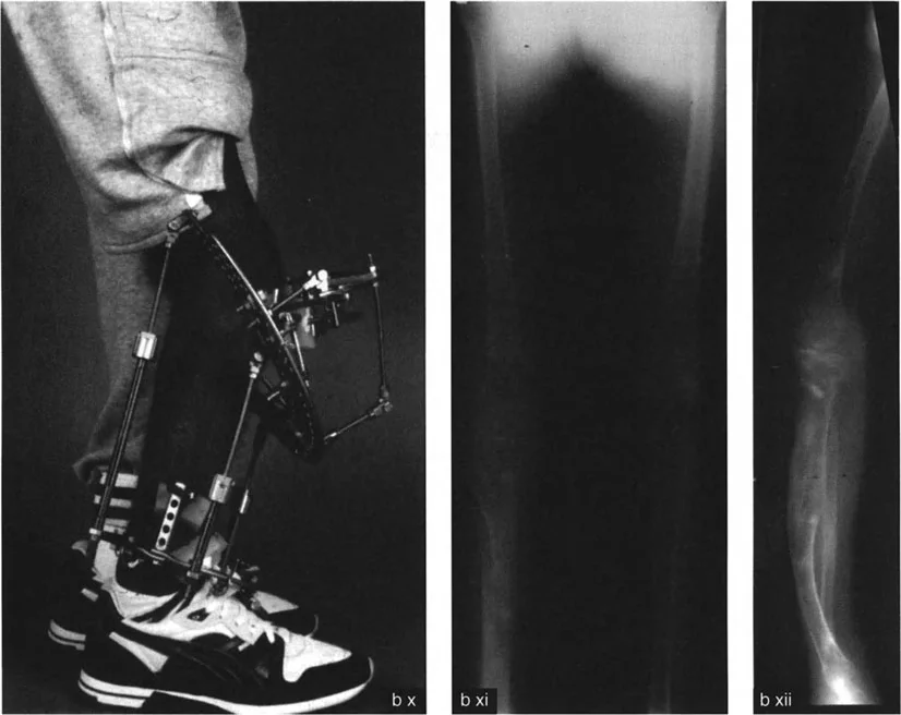
Determine how the osteotomy will be stabilized once the bone is rotated. Acute corrections of this magnitude typically require robust internal fixation. Pre-contoured locking plates are often the implant of choice, though intramedullary nails can be used if the osteotomy is diaphyseal and the canal diameter allows for the rotation.
Surgical Execution of the Paley Single Cut Technique
Transitioning from the preoperative blueprint to the physical execution requires extreme precision. The mathematical elegance of the plan will fail if the saw cut deviates by even a few degrees.
Pin Placement and Axis Orientation
Once the bone is exposed, the first critical step is placing the guide pins. These pins will dictate the plane of the osteotomy.
1. Place a reference pin perfectly parallel to the proximal joint line.
2. Perform the R/2 maneuver. If the rotational deformity is 20 degrees of internal rotation, rotate your guide pin 10 degrees externally relative to the reference pin.
3. Incline the pin according to your calculated osteotomy inclination angle (e.g., 61 degrees).
4. Verify the pin placement with intraoperative fluoroscopy in both the AP and lateral planes.
Performing the Osteotomy
The osteotomy must be perfectly planar. A wandering saw blade will create a curved cut, making smooth rotation impossible and resulting in poor bone apposition.
* Use a sharp, stiff saw blade to prevent deflection.
* Irrigate the blade continuously with cold saline to prevent thermal necrosis of the bone, which can lead to delayed union or nonunion.
* Complete the cut entirely through the far cortex. Do not attempt to crack the far cortex, as a greenstick fracture will tether the rotation and force the bone out of the intended correction plane.
The Rotation Maneuver and Fixation
Once the bone is completely sectioned, insert a Shanz pin into the proximal segment and another into the distal segment. Use these pins as joysticks to rotate the distal segment around the central axis of the bone.
As you rotate the distal segment, you will visually observe the angular deformity correcting simultaneously. Continue the rotation until the distal joint axis is perfectly aligned with the proximal joint axis. Temporarily hold the correction with rigid K-wires.
Verify the correction fluoroscopically. Use an alignment rod (electrocautery cord) over the draped limb to confirm that the Mechanical Axis Deviation has been restored to neutral. Once confirmed, apply your pre-selected rigid internal fixation.
Clinical Pearls for Multiplanar Correction
For surgeons mastering this technique, several high-yield clinical pearls can mean the difference between a perfect outcome and a frustrating complication.
- Respect the Soft Tissues Acute correction of large angular and rotational deformities places immense stress on the neurovascular structures. Always assess the peroneal nerve when correcting severe valgus and internal rotation deformities. Prophylactic peroneal nerve decompression may be indicated.
- The R/2 Rule is Absolute Forgetting to reorient the saw blade by half the rotational deformity before inclining the cut is the most common mathematical error in the operating room. This will result in an imperfect correction plane.
- Account for Saw Blade Thickness The thickness of the saw blade removes bone. In highly precise corrections, this minimal bone loss can cause a slight shortening or translation. Always ensure the bone ends are firmly compressed after rotation.
- Verify with the Cable Method Intraoperatively, always run a radiopaque cable from the center of the femoral head to the center of the ankle under fluoroscopy to confirm that the mechanical axis passes through the desired coordinate in the knee.
Overcoming Common Surgical Pitfalls
Even with meticulous planning, pitfalls can occur during the execution of a single inclined osteotomy. Recognizing and mitigating these errors intraoperatively is a hallmark of an expert deformity surgeon.
Undercorrection of the Deformity
Undercorrection typically occurs when the surgeon fails to rotate the bone through the full calculated hypotenuse of the deformity. Because the soft tissues resist the acute rotation, the surgeon may stop prematurely. Ensure that the distal joint line is fully reoriented before applying definitive fixation.
Hinge Failure and Translation
If the saw cut is not perfectly straight, the bone ends will not glide smoothly against each other during rotation. This leads to gapping at the osteotomy site and unintended translation (violating Paley's Osteotomy Rules). If the cut is non-planar, the surgeon may need to use a high-speed burr to meticulously smooth the bone ends, though this sacrifices length.
Delayed Union
The single inclined osteotomy relies on excellent cortical contact for stability and healing. If the rotation creates a geometric mismatch (which can occur in diaphyseal cuts where the bone is not perfectly cylindrical), the contact area decreases. Maximize stability with compression plating and consider local bone grafting if the contact area is less than 70 percent.
Conclusion
Mastering the Paley Single-Cut Osteotomy Technique for angulation-rotation deformities elevates an orthopedic surgeon's capability from basic fracture management to advanced limb reconstruction. By internalizing the concepts of the Center of Rotation of Angulation, the Mechanical Axis Deviation, and the trigonometric relationships defined by the Banana Analogy, surgeons can confidently tackle the most daunting three-dimensional deformities.
The transition from multi-staged, complex external fixation frames to a single, mathematically precise internal osteotomy represents one of the great leaps forward in modern orthopedic surgery. Through rigorous preoperative planning, strict adherence to the osteotomy rules, and flawless intraoperative execution, surgeons can restore normal biomechanics, prevent joint degeneration, and profoundly improve their patients' quality of life.
!!! info "Academic Resource & Medical Review"
This academic resource was prepared and medically reviewed by Prof. Dr. Mohammed Hutaif, Consultant Orthopedic & Spine Surgeon. It is formulated specifically for medical students, orthopedic residents, and surgeons preparing for high-stakes board examinations (AAOS, FRCS Tr & Orth, Arab Board).
!!! warning "Disclaimer"
The surgical techniques, classifications, and clinical guidelines presented herein are for educational and academic review purposes only. They are not intended to replace institutional protocols or independent clinical judgment.
You Might Also Like