Mastering Frontal Plane Realignment: Paley's Principles for Precision Osteotomy
Key Takeaway
Frontal plane realignment corrects lower extremity deformities by restoring physiological joint angles. Dr. Paley's principles guide precise osteotomy planning using CORA and ACA to restore the mechanical axis. This prevents secondary deformities, ensuring optimal orthopedic outcomes.
Introduction to Frontal Plane Realignment and Deformity Correction
Orthopedic deformity correction is an unforgiving discipline that requires a profound understanding of biomechanics, geometry, and spatial relationships. At the heart of modern deformity correction are the principles popularized by Dr. Dror Paley. Mastering frontal plane realignment is an essential skill for any orthopedic surgeon, whether you are performing a High Tibial Osteotomy (HTO) for medial compartment gonarthrosis, correcting a post-traumatic distal femoral malunion, or managing congenital pediatric deformities.
When a lower extremity deviates from its normal mechanical axis, the resulting Mechanical Axis Deviation (MAD) alters the load-bearing mechanics of the knee, hip, and ankle joints. Medial MAD leads to varus deformity and medial compartment overload, while lateral MAD leads to valgus deformity and lateral compartment overload. The goal of an osteotomy is not merely to make a bone look straight on a radiograph, but to meticulously restore the joint orientation angles to their physiological norms.
To achieve this, surgeons must transition from eyeballing corrections to utilizing a strict geometric framework. This comprehensive guide will decode the foundational osteotomy concepts, focusing on the Center of Rotation of Angulation (CORA), the Angulation Correction Axis (ACA), the profound effects of translation and length displacement, and the strict application of Paleys Osteotomy Rules.
Understanding Mechanical Axis Deviation and Joint Orientation Angles
Before any surgical intervention is planned, the surgeon must quantify the deformity. The mechanical axis of the lower extremity is defined by a line drawn from the center of the femoral head to the center of the ankle joint (the center of the tibial plafond). In a physiologically normal limb, this line should pass just medial to the center of the knee joint.
Mechanical Axis Deviation is the distance in millimeters from the center of the knee joint to this mechanical axis line. Quantifying the MAD is the first step in the Malalignment Test. Once malalignment is confirmed, the surgeon must perform the Malorientation Test to determine whether the deformity originates in the femur, the tibia, or the knee joint itself.
This is achieved by measuring the Joint Orientation Angles. These angles define the relationship between the mechanical axes of the bones and their respective joint lines in the frontal plane.
Key Frontal Plane Joint Orientation Angles
- Mechanical Lateral Distal Femoral Angle (mLDFA): The lateral angle formed by the mechanical axis of the femur and the distal femoral joint line.
- Medial Proximal Tibial Angle (MPTA): The medial angle formed by the mechanical axis of the tibia and the proximal tibial joint line.
- Lateral Distal Tibial Angle (LDTA): The lateral angle formed by the mechanical axis of the tibia and the distal tibial joint line.
- Joint Line Convergence Angle (JLCA): The angle formed between the distal femoral joint line and the proximal tibial joint line. This measures intra-articular deformity or ligamentous laxity.
Normal Values for Joint Orientation Angles
| Angle Designation | Normal Range | Average Value | Clinical Significance |
|---|---|---|---|
| mLDFA | 85 to 90 degrees | 87.5 degrees | Identifies distal femoral varus or valgus |
| MPTA | 85 to 90 degrees | 87.5 degrees | Identifies proximal tibial varus or valgus |
| LDTA | 86 to 92 degrees | 89 degrees | Identifies distal tibial varus or valgus |
| JLCA | 0 to 2 degrees | 0 to 1 degree | Identifies intra-articular laxity or cartilage loss |
Restoring these angles to their normal parameters is the ultimate biological and biomechanical goal of any frontal plane realignment procedure.
The Foundational Geometry of Deformity Correction
Before executing a bony cut, the surgeon must map the deformity using specific geometric lines and points. The transition from intuitive surgery to precision surgery relies entirely on understanding these structural landmarks.
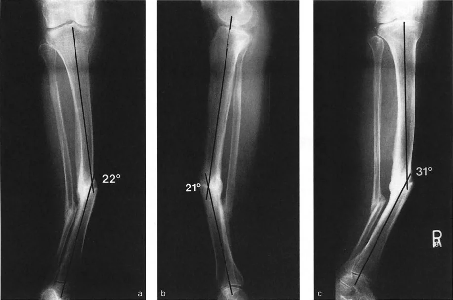
Center of Rotation of Angulation
The CORA is the intersection point of the proximal and distal mechanical (or anatomical) axes of a deformed bone. It represents the true apex of the deformity. Identifying the CORA is the most critical step in preoperative planning.
A bone may have a single CORA, known as a uniapical deformity, or multiple CORAs, known as a multiapical deformity. In multiapical deformities, the surgeon must draw the axes of the proximal segment, the middle segment, and the distal segment to identify each individual apex. Failure to recognize a multiapical deformity often leads to the creation of a secondary translational deformity when a single osteotomy is mistakenly applied.
Transverse and Longitudinal Bisector Lines
Once the CORA is identified, the magnitude of the deformity angle is measured. To plan the correction, the surgeon must construct a localized coordinate system around the CORA.
- Transverse Bisector Line (tBL): A line drawn exactly through the CORA that bisects the obtuse angle of the intersecting proximal and distal axes.
- Longitudinal Bisector Line (lBL): A line drawn through the CORA that bisects the acute angle of the intersecting axes. It is exactly perpendicular to the tBL.
These bisector lines are not merely theoretical constructs. They dictate the exact trajectory of bone segment movement during the physical correction of the deformity.
Angulation Correction Axis Dynamics
While the CORA is a static geometric point determining where the deformity originates, the Angulation Correction Axis (ACA) is the dynamic mechanical axis around which the surgeon physically rotates the bone segments to achieve correction. The relationship between the osteotomy cut, the CORA, and the ACA forms the basis of all modern deformity correction.
In external fixation (such as a Taylor Spatial Frame or Ilizarov apparatus), the ACA corresponds to the physical hinge placed by the surgeon. In internal fixation (such as opening wedge high tibial osteotomies), the ACA corresponds to the intact cortical hinge.
Translation and Length Displacement at the Osteotomy Line
A common pitfall in orthopedic surgery is failing to account for unintended translation or length changes when correcting an angular deformity. The amount of change in length or translation of points on the osteotomy line for any given ACA can be determined graphically.
When the correction is performed around an ACA that is offset from the central axis of the bone, the bone ends will undergo a predictable geometric shift. To visualize this, imagine a Cartesian coordinate graph where the ACA is at the origin.
The orthogonal axes of this graph are lines parallel to the tBL and lBL, centered directly on the ACA. These are referred to as the modified transverse bisector line and modified longitudinal bisector line.
The Kinematics of the ACA Graph
- Translation Dynamics: Every point on the bone proximal to the modified transverse bisector line will translate in one direction, and every point distal to it will translate in the opposite direction.
- Length Dynamics: Similarly, every point convex to the modified longitudinal bisector line will be distracted (resulting in lengthening), and every point concave to it will be compressed (resulting in shortening).
If the deformity angle is extended from the CORA toward these modified bisector lines, we can measure the exact spatial changes. Let the variable L be the distance between the arms of the angle as measured on the transverse line, and T be the distance measured on the longitudinal line. If the correction is performed around this specific ACA, the bone ends will lengthen apart by distance L and translate by distance T. Understanding this Cartesian relationship is critical when planning external fixator hinges or positioning internal plates.
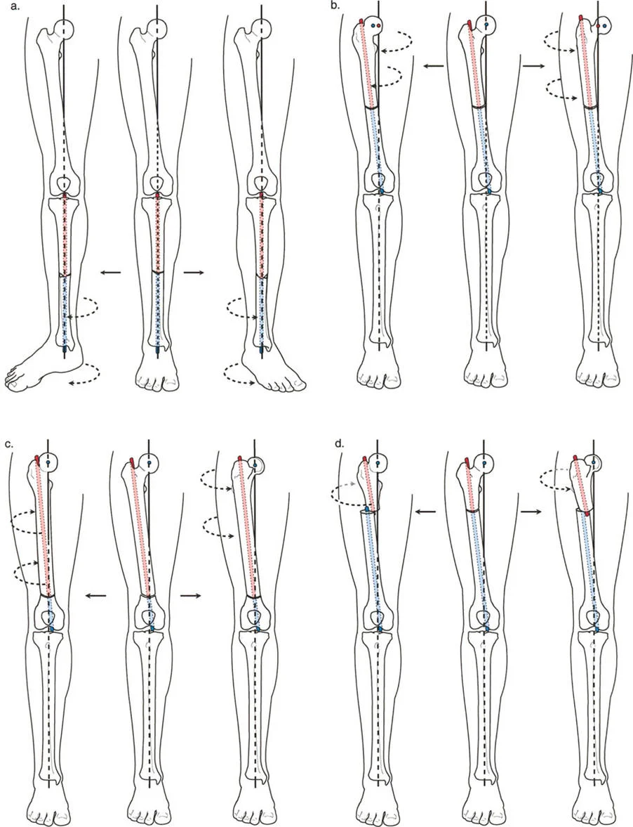
Paleys Three Osteotomy Rules
To control the kinematics described above, Dr. Dror Paley formalized three immutable geometric rules. Mastering these rules allows the surgeon to predict exactly how the bone segments will behave once the osteotomy is completed and the correction is applied.
Osteotomy Rule One
The Rule: The osteotomy line and the ACA both pass directly through the CORA.
The Result: The bone segments will undergo pure angulation around the CORA. The proximal and distal mechanical axes will perfectly realign without any translation.
Clinical Application: This is the ideal scenario for most deformity corrections. It ensures that the mechanical axis is restored without creating secondary step-offs in the bone contour.
Osteotomy Rule Two
The Rule: The ACA passes through the CORA, but the osteotomy line is placed at a different level (either proximal or distal to the CORA).
The Result: The mechanical axes will perfectly realign, but the bone ends at the osteotomy site will undergo obligatory translation.
Clinical Application: This rule is frequently used when the CORA is located very close to a joint line (where there is inadequate room for hardware fixation) or in poor quality bone. The surgeon intentionally performs the osteotomy in healthy diaphyseal bone while keeping the hinge (ACA) at the joint line CORA. The surgeon must anticipate and accept the resulting cortical step-off (translation) at the osteotomy site.
Osteotomy Rule Three
The Rule: The osteotomy line and the ACA are both placed at a level different from the CORA.
The Result: The mechanical axes will not perfectly realign; instead, they will translate parallel to one another. This creates a secondary translational deformity.
Clinical Application: Rule Three is generally considered a surgical error if done unintentionally. However, it can be used deliberately to correct a pre-existing translational deformity alongside an angular deformity. By placing the ACA off the CORA, the surgeon can induce a translation that cancels out the patients existing translation.
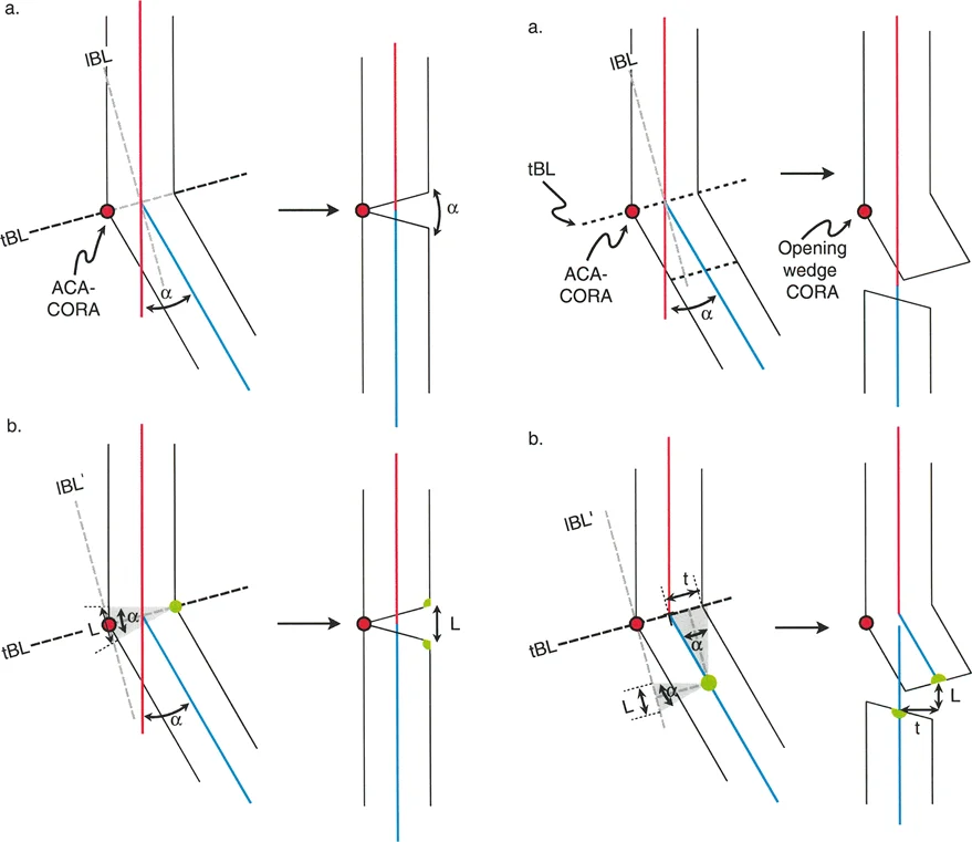
Biomechanics of the Opening Wedge Osteotomy
The opening wedge osteotomy is a powerhouse technique in frontal plane realignment, frequently utilized in the proximal tibia to correct varus deformities.
Dynamics of the Opening Wedge
The defining characteristic of an opening wedge osteotomy is the placement of the ACA. The ACA-CORA is positioned at the convex cortex of the bone on the transverse bisector line. This specific point is called the opening wedge point or opening wedge CORA.
When the osteotomy line passes through this point, the convex cortex acts as an intact hinge (or a closely approximated pseudo-hinge). Because the axis of rotation is on the far convex side, the entire correction occurs via distraction.
- The convex cortex remains in contact, acting as the fulcrum.
- A wedge-shaped bone defect is created, with its base on the concave side.
- All points on the convex side of the ACA-CORA are subjected to compression (though they are already in contact).
- All points on the concave side of the ACA-CORA are distracted.
Clinical Implications and Nerve Management
The final length of the bone is dictated by its convex cortex. Because the concave side is distracted to match the convex side, an opening wedge osteotomy inherently lengthens the bone. This is highly advantageous in patients with a concomitant leg length discrepancy where the deformed leg is shorter.
However, it can be dangerous if it places excessive tension on neurovascular structures, such as stretching the common peroneal nerve during proximal tibial corrections. A large medial opening wedge high tibial osteotomy can stretch the peroneal nerve laterally. Surgeons must be vigilant and consider a prophylactic peroneal nerve decompression if the opening wedge correction exceeds 10 to 12 millimeters, or if the patient has a high risk of compartment syndrome.
Furthermore, opening wedge osteotomies require structural support to maintain the correction. This usually mandates the use of structural bone graft (autograft, allograft, or synthetic substitutes) and rigid internal plate fixation to prevent collapse of the distracted gap while bone healing occurs.
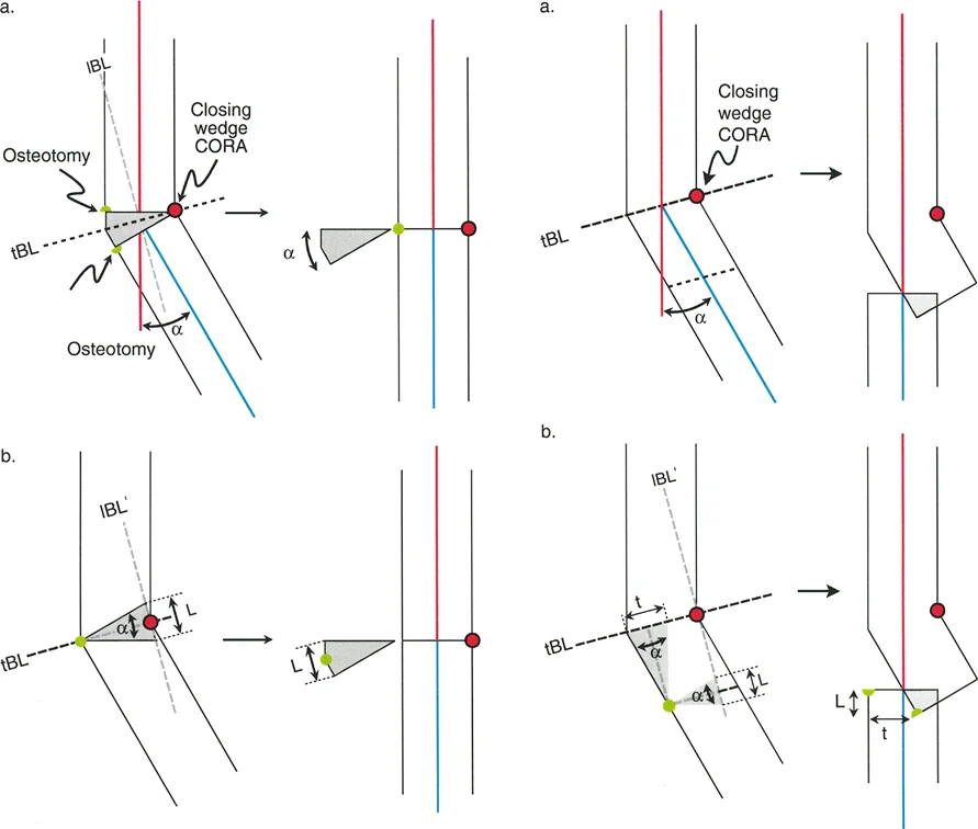
Biomechanics of the Closing Wedge Osteotomy
To fully understand frontal plane realignment, one must contrast the opening wedge with the closing wedge osteotomy. While the opening wedge relies on distraction, the closing wedge relies on compression and bone resection.
Dynamics of the Closing Wedge
In a closing wedge osteotomy, the ACA is positioned on the concave cortex of the bone. The surgeon removes a meticulously measured wedge of bone from the convex side, and the gap is closed down until the two cut surfaces meet.
- The concave cortex acts as the intact hinge.
- A wedge of bone is physically resected from the convex side.
- The correction occurs entirely through compression.
- No structural bone graft is required because the bone ends are brought into direct cortical contact.
Clinical Implications of the Closing Wedge
Because the correction relies on bringing the convex side down to match the concave side, a closing wedge osteotomy inherently shortens the bone. This makes it an excellent choice for a patient with a varus deformity who also has a leg length discrepancy where the deformed leg is longer.
Closing wedge osteotomies generally heal faster than opening wedge osteotomies because they rely on direct cortical contact and compression, which provides high inherent stability. However, the procedure is technically demanding. Resecting the exact geometry of the wedge is difficult, and over-resection or under-resection can lead to severe malalignment. Additionally, in the proximal tibia, a lateral closing wedge osteotomy requires a concomitant proximal tibiofibular joint disruption or a fibular osteotomy to allow the tibia to close properly.
Biomechanics of the Neutral Wedge Osteotomy
There is a third option that balances the biomechanical effects of the opening and closing wedges: the neutral wedge osteotomy.
Dynamics of the Neutral Wedge
In a neutral wedge osteotomy, the ACA is placed exactly in the center of the bone (the central anatomical axis). Because the axis of rotation is central, the correction involves a combination of both opening and closing mechanics.
- The convex half of the bone undergoes compression (closing wedge).
- The concave half of the bone undergoes distraction (opening wedge).
- The overall length of the bone remains completely unchanged.
Clinical Execution via Dome Osteotomy
In clinical practice, a true neutral wedge is difficult to achieve with straight transverse cuts because the bone ends would impinge on one side and gap on the other, leading to poor stability. Therefore, neutral wedge corrections are typically executed using a dome osteotomy (or focal dome osteotomy).
The surgeon makes a semi-circular cut (cylindrical in three dimensions) whose center of rotation corresponds exactly to the CORA. The bone segments are then rotated along this curved path. This allows for massive angular corrections without altering limb length and without creating large bone voids that require grafting. Dome osteotomies are highly stable due to the large surface area of bone contact and are frequently stabilized with external fixators or specialized intramedullary nails.
Step by Step Preoperative Planning for Frontal Plane Realignment
Mastering the theory is only the first half of the battle. The surgeon must apply these principles systematically during preoperative planning. Haphazard planning leads to intraoperative confusion and postoperative malalignment.
Step 1 Obtain Proper Imaging
Accurate planning requires high-quality, full-length, weight-bearing radiographs of the lower extremities. The patella must be facing strictly forward (the patella forward position) to eliminate rotational artifact, which can artificially alter the appearance of frontal plane alignment.
Step 2 Perform the Malalignment Test
Draw the mechanical axis of the entire lower limb from the center of the femoral head to the center of the ankle. Measure the Mechanical Axis Deviation (MAD). If the line falls medial to the center of the knee, the patient has a varus deformity. If it falls lateral, the patient has a valgus deformity.
Step 3 Perform the Malorientation Test
Draw the individual mechanical axes of the femur and the tibia. Measure the mLDFA, MPTA, and JLCA. Compare these measurements to the normal physiological values to isolate the source of the deformity.
Step 4 Identify the CORA
Extend the normal proximal mechanical axis and the abnormal distal mechanical axis until they intersect. This intersection point is the CORA. Determine if the deformity is uniapical or multiapical.
Step 5 Determine the Osteotomy Rule and ACA
Decide where the physical bone cut will be made based on bone quality, soft tissue envelope, and hardware requirements.
* If the cut can be made at the CORA, apply Osteotomy Rule One.
* If the cut must be made away from the CORA, apply Osteotomy Rule Two and calculate the expected translation.
* Choose your ACA location (convex cortex, concave cortex, or central) based on whether you want to lengthen, shorten, or maintain limb length.
Step 6 Simulate the Correction
Using digital templating software (or traditional tracing paper), simulate the osteotomy. Rotate the distal segment around your chosen ACA until the mechanical axes align perfectly. Verify that the joint orientation angles have been restored to normal and assess the final bone contour.
Clinical Pearls for Successful Osteotomy Execution
Translating a perfect preoperative plan into a flawless surgical execution requires meticulous attention to detail in the operating room.
- Respect the Hinge: Whether using an internal plate or an external fixator, the hinge is the most critical element of the correction. If performing an opening wedge osteotomy, leave at least 10 millimeters of intact lateral cortex to serve as a robust hinge. If the hinge fractures completely, you lose rotational stability and the ACA shifts unpredictably.
- Manage the Soft Tissues: Deformity correction is not just about bone. Chronic deformities result in soft tissue contractures on the concave side and laxity on the convex side. Be prepared to perform prophylactic fasciotomies, nerve decompressions, or tendon lengthenings.
- Account for the JLCA: A wide Joint Line Convergence Angle indicates intra-articular deformity or ligamentous laxity. If a patient has a varus thrust due to lateral collateral ligament laxity, correcting the bony MPTA alone will not fully resolve the mechanical axis deviation. You must slightly over-correct the bony anatomy to compensate for the soft tissue laxity.
- Use Temporary Fixation: Before applying definitive rigid plates, use temporary Kirschner wires to hold the correction. Drop a sterile alignment rod (or use an electrocautery cord) over the leg under fluoroscopy to confirm that the mechanical axis now passes through the desired coordinate of the knee joint.
- Beware of the Sagittal Plane: This guide focuses on frontal plane realignment, but bones exist in three dimensions. An opening wedge osteotomy in the proximal tibia will inherently increase the posterior tibial slope if the gap is opened symmetrically. To maintain the native sagittal slope, the anterior gap must be opened approximately half as much as the posteromedial gap.
Conclusion on Mastering Paleys Principles
Orthopedic deformity correction is a mathematical discipline disguised as surgery. The principles established by Dr. Dror Paley provide a universal language and a foolproof geometric framework for analyzing and correcting any lower extremity deformity.
By mastering the concepts of the CORA, the Angulation Correction Axis, and the kinematics of translation and length displacement, surgeons can eliminate the guesswork from their procedures. Whether executing a simple uniapical opening wedge osteotomy or managing a complex multiapical post-traumatic deformity, strict adherence to Paleys Osteotomy Rules ensures precise restoration of the mechanical axis, normalization of joint orientation angles, and optimal functional outcomes for the patient.
!!! info "Academic Resource & Medical Review"
This academic resource was prepared and medically reviewed by Prof. Dr. Mohammed Hutaif, Consultant Orthopedic & Spine Surgeon. It is formulated specifically for medical students, orthopedic residents, and surgeons preparing for high-stakes board examinations (AAOS, FRCS Tr & Orth, Arab Board).
!!! warning "Disclaimer"
The surgical techniques, classifications, and clinical guidelines presented herein are for educational and academic review purposes only. They are not intended to replace institutional protocols or independent clinical judgment.
You Might Also Like