Mastering Orthopedic Deformity Correction: Paley's CORA & Axis Planning
Key Takeaway
Paley's CORA principles are a systematized approach for orthopedic deformity correction. They involve mechanical and anatomic axis planning to identify the Center of Rotation of Angulation (CORA). This guides precise osteotomy placement, restoring normal limb alignment and preventing iatrogenic translation.
Introduction to Frontal Plane Deformity Correction
For the orthopedic surgeon, mastering deformity correction is akin to mastering the fundamental language of the musculoskeletal system. At the heart of this discipline lies the work of Dr Dror Paley, whose systematized approach to mechanical and anatomic axis planning revolutionized how we understand, quantify, and surgically correct complex limb deformities. Before the codification of these principles, osteotomies were often performed based on visual estimation or "eyeballing," leading to unpredictable outcomes and iatrogenic mechanical axis deviations.
In this comprehensive masterclass, we will deconstruct the principles of Frontal Plane Mechanical and Anatomic Axis Planning. We will move beyond rote memorization of angles and dive deep into the biomechanical rationale, surgical applications, and nuanced problem solving required when facing post traumatic malunions, congenital deformities, and complex multiapical angulations.
Whether you are planning a high tibial osteotomy, a distal femoral osteotomy, or utilizing a hexapod circular fixator, the principles outlined in this guide will serve as your definitive roadmap. The core of this methodology centers on identifying the Center of Rotation of Angulation and applying precise geometric rules to restore normal limb alignment without inducing secondary translational deformities.
Biomechanical Foundations of the Frontal Plane
Before drawing a single line on a radiograph, a surgeon must understand the biomechanical goals of deformity correction. The primary objective is to restore the Mechanical Axis Deviation to normal, ensuring that the ground reaction force vector passes through the center of the knee joint. This optimizes load distribution across the medial and lateral compartments, preventing premature osteoarthritis, meniscal degradation, and ligamentous overload.
Understanding Mechanical Axis Deviation
The mechanical axis of the lower extremity is the weight bearing line of the limb. On a standing full length anteroposterior radiograph, this line is drawn from the center of the femoral head to the center of the ankle plafond. In a normal, non deformed limb, this line should pass slightly medial to the center of the knee joint, typically 8 to 10 millimeters medial to the midline of the tibial plateau.
When a deformity exists, this weight bearing line shifts.
* Varus Deformity: The mechanical axis shifts further medial to the knee center, increasing the compressive forces on the medial compartment and placing tensile stress on the lateral collateral ligament complex.
* Valgus Deformity: The mechanical axis shifts lateral to the knee center, overloading the lateral compartment cartilage and stressing the medial collateral ligament.
Quantifying the Mechanical Axis Deviation is the first step in the Malalignment Test. If the Mechanical Axis Deviation falls outside the normal physiological range, the surgeon must systematically evaluate the femur and the tibia to isolate the source of the deformity.
The Mechanical Versus Anatomic Axis
Understanding the distinction between the mechanical and anatomic axes is paramount for executing Paley deformity planning accurately. Confusing these two lines is a common pitfall for junior residents and can lead to disastrous surgical outcomes.
Defining the Axes
- Mechanical Axis: A line connecting the center points of the proximal and distal joints of a given bone. For the femur, it connects the center of the femoral head to the center of the knee joint (specifically, the midpoint between the femoral condyles). For the tibia, it connects the center of the tibial plateau to the center of the tibial plafond.
- Anatomic Axis: A line that bisects the medullary canal, also known as the mid diaphyseal line. This line represents the physical shaft of the bone.
The Anatomic Mechanical Angle
The relationship between the mechanical and anatomic axes is defined by the Anatomic Mechanical Angle.
In the tibia, the mechanical and anatomic axes are essentially parallel and superimposed. Therefore, the tibial Anatomic Mechanical Angle is effectively 0 degrees. Because of this parallel relationship, surgeons can often use the anatomic axis as a reliable proxy for the mechanical axis when planning tibial corrections.
In the femur, however, the anatomic axis diverges from the mechanical axis. Because the femoral neck offsets the femoral head medially, the mechanical axis drops at an angle relative to the femoral shaft. The average femoral Anatomic Mechanical Angle is 7 degrees, though it can range from 5 to 9 degrees depending on patient height and pelvic width. This simple geometric fact explains why femoral planning is inherently more complex than tibial planning. You cannot simply use the intramedullary canal of the femur to dictate your mechanical alignment without accounting for this 7 degree offset.
Key Joint Orientation Angles
To execute Paley planning methods, you must commit the normal population averages of joint orientation angles to memory. They are the reference points used to determine if a bone segment is deformed and to draw the normal reference lines during reverse planning.
Below is a comprehensive summary table of the critical frontal plane joint orientation angles.
| Angle Abbreviation | Full Name | Average Value | Normal Range |
|---|---|---|---|
| mLDFA | Mechanical Lateral Distal Femoral Angle | 87° | 85° – 90° |
| MPTA | Mechanical Proximal Tibial Angle | 87° | 85° – 90° |
| LPFA | Lateral Proximal Femoral Angle | 90° | 85° – 95° |
| LDTA | Lateral Distal Tibial Angle | 89° | 86° – 92° |
| aLDFA | Anatomic Lateral Distal Femoral Angle | 81° | 79° – 83° |
| MPFA | Mechanical Proximal Femoral Angle | 84° | 80° – 89° |
| JLCA | Joint Line Convergence Angle | 0° | 0° – 2° |
Clinical Significance of Joint Angles
When evaluating a limb with an abnormal Mechanical Axis Deviation, the surgeon must measure the mLDFA and the MPTA.
- If the Mechanical Axis Deviation is in varus, and the MPTA is 80 degrees (normal 87), the deformity is located in the proximal tibia.
- If the Mechanical Axis Deviation is in valgus, and the mLDFA is 80 degrees (normal 87), the deformity is located in the distal femur.
These angles dictate where the deformity lives. It is entirely possible to have a combined deformity where both the femur and the tibia contribute to the overall malalignment. In such cases, measuring these specific joint orientation angles isolates the exact magnitude of deformity in each respective bone, allowing for a precise, multi level surgical correction plan.
Principles of the Center of Rotation of Angulation
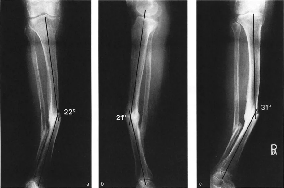
The Center of Rotation of Angulation is the foundational concept of modern deformity correction. By definition, the Center of Rotation of Angulation is the point at which the proximal axis of a bone intersects with the distal axis of a bone.
When a bone fractures and heals in a malunion, or when a bone bows due to a congenital defect, the proximal segment and the distal segment are no longer collinear. If you draw a line representing the axis of the proximal segment and a line representing the axis of the distal segment, they will cross. That intersection point is the Center of Rotation of Angulation.
The angle formed by this intersection represents the true magnitude of the deformity. Furthermore, if you bisect this angle, you create the transverse bisector line. The transverse bisector line is a critical surgical landmark because it dictates where your osteotomy and your hinges should be placed to achieve a perfect correction.
Paley Osteotomy Rules
Dr Paley established three fundamental rules regarding the relationship between the Center of Rotation of Angulation, the osteotomy site, and the Axis of Correction of Angulation. The Axis of Correction of Angulation is the actual physical hinge point around which the bone is turned during surgery. Understanding these rules is mandatory for preventing iatrogenic translation.
Rule 1
When the osteotomy and the Axis of Correction of Angulation are both placed precisely at the Center of Rotation of Angulation, the deformity corrects with pure angulation. The bone ends will remain perfectly apposed without any translation. This is the ideal scenario for an opening wedge or closing wedge osteotomy performed at the apex of the deformity.
Rule 2
When the Axis of Correction of Angulation is placed at the Center of Rotation of Angulation, but the osteotomy is performed at a different level, the deformity will correct with a combination of angulation and translation. The mechanical axis will be perfectly restored, but the bone ends at the osteotomy site will be offset. This is often necessary when the Center of Rotation of Angulation is located very close to a joint line, making fixation difficult. By using a focal dome osteotomy or a hexapod frame, the surgeon can cut the bone in the diaphysis but hinge it around the joint, resulting in intentional, corrective translation.
Rule 3
When the osteotomy and the Axis of Correction of Angulation are both placed away from the Center of Rotation of Angulation, the correction will result in an iatrogenic translation deformity. The mechanical axis of the proximal and distal segments will remain parallel but will not be collinear. This is a surgical error and leads to a "zig zag" deformity, which can compromise the final mechanical axis of the entire limb.
Tibial Anatomic Axis Planning
Anatomic axis planning in the tibia is highly practical, particularly when the surgical plan involves intramedullary nailing. Because the rigid intramedullary nail will dictate the alignment of the medullary canal, planning around the anatomic mid diaphyseal lines allows the surgeon to accurately predict the postoperative alignment.
Anatomic axis planning is predominantly utilized for post fracture deformities and diaphyseal malunions. The goal here is to restore the pre fracture diaphyseal alignment rather than altering the native, pre existing joint orientation.
Step by Step Tibial Anatomic Planning
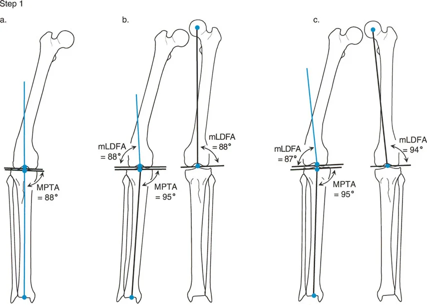
Step 1 Draw the Mid Diaphyseal Lines
Begin by identifying the center of the medullary canal in the proximal segment of the deformed tibia. Place several dots in the center of the canal and connect them to form the proximal anatomic axis line. Repeat this process for the distal segment of the tibia to create the distal anatomic axis line.
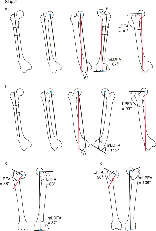
Step 2 Evaluate Joint Orientation
You must determine if the proximal and distal joint lines are normally oriented relative to their respective diaphyseal segments.
* Proximal Evaluation: Draw the knee joint line across the flat portions of the medial and lateral tibial plateaus. Measure the Mechanical Proximal Tibial Angle between this joint line and your proximal anatomic axis line. If the MPTA is normal, the proximal mid diaphyseal line is your true proximal anatomic axis. If the MPTA is abnormal, you must draw a new anatomic axis line referenced off the knee joint line. Use the contralateral normal MPTA as a template. If the contralateral side is unavailable, use the population average of 87 degrees.
* Distal Evaluation: Draw the ankle joint line across the flat subchondral bone of the tibial plafond. Measure the Lateral Distal Tibial Angle to the distal most tibial mid diaphyseal line. If the LDTA is normal, there is no further distal deformity. If the LDTA is abnormal, draw a new anatomic axis line referenced to the ankle joint orientation line. Note that the starting point for the tibial anatomic axis at the ankle is typically 4 millimeters medial to the center of the ankle joint.
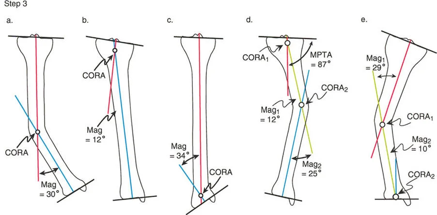
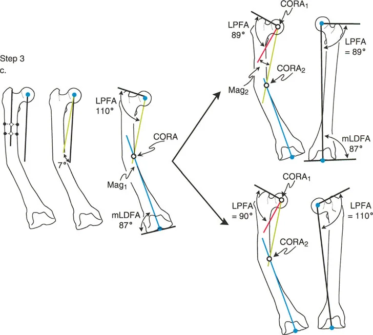
Step 3 Identify the CORA and Measure Magnitude
Decide whether the deformity is uniapical or multiapical based on how the lines intersect.
- Uniapical Deformity: If there is only one pair of anatomic axis lines drawn, they will intersect at a single point. This intersection is the Center of Rotation of Angulation. Measure the angle between these lines to determine the exact magnitude of the deformity in degrees.
- Multiapical Deformity: For each additional anatomic axis line required due to abnormal joint angles or complex diaphyseal bowing, there will be an additional intersection point. Each intersection represents a separate Center of Rotation of Angulation with its own magnitude.
Femoral Mechanical Axis Planning
Femoral mechanical axis planning is the gold standard for correcting complex lower limb malalignment. Unlike the tibia, where the anatomic axis is frequently used, the femur's inherent 7 degree Anatomic Mechanical Angle makes anatomic planning cumbersome and prone to error, especially for periarticular deformities. Mechanical axis planning directly addresses the weight bearing line of the limb, making it the most robust method for ensuring optimal joint loading.
Mechanical axis planning utilizes a "reverse planning" methodology. Instead of drawing lines through the center of the deformed bone, the surgeon draws lines based on where the normal mechanical axis should be, referenced off the joint lines.
Step by Step Femoral Mechanical Planning
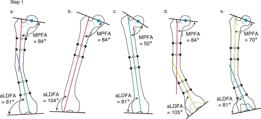
Step 1 Establish the Joint Lines
First, identify and draw the proximal and distal joint lines of the femur.
* Proximal Joint Line: Draw a line connecting the tip of the greater trochanter to the center of the femoral head. This helps establish the Lateral Proximal Femoral Angle.
* Distal Joint Line: Draw a line tangential to the most distal points of the medial and lateral femoral condyles.
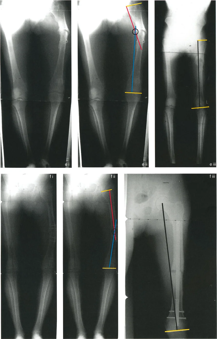
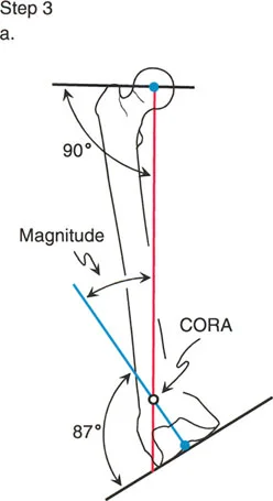
Step 2 Draw the Proximal Mechanical Axis
Locate the center of the femoral head. Using a goniometer or digital templating software, draw a line originating from the center of the femoral head downward, intersecting the proximal joint line at an angle of 90 degrees. This 90 degree angle represents the normal Lateral Proximal Femoral Angle. Extend this line distally down the length of the femur. This is your proximal mechanical axis line.
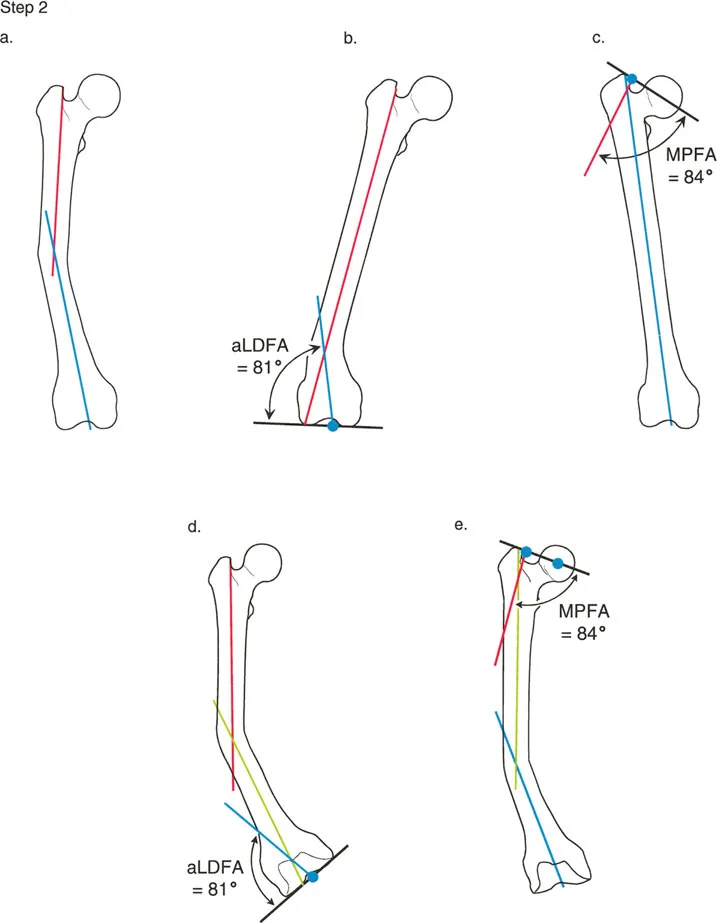
Step 3 Draw the Distal Mechanical Axis
Locate the center of the knee joint, which is the midpoint between the medial and lateral femoral condyles. From this point, draw a line extending proximally, intersecting the distal femoral joint line at an angle of 87 degrees. This 87 degree angle represents the normal Mechanical Lateral Distal Femoral Angle. Extend this line proximally up the shaft of the femur. This is your distal mechanical axis line.
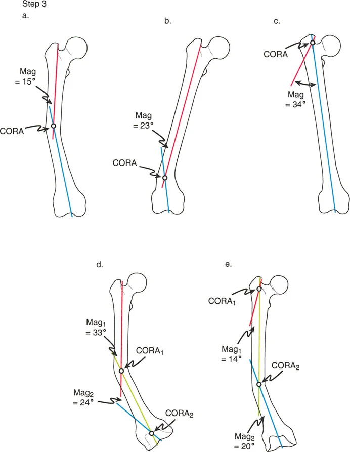
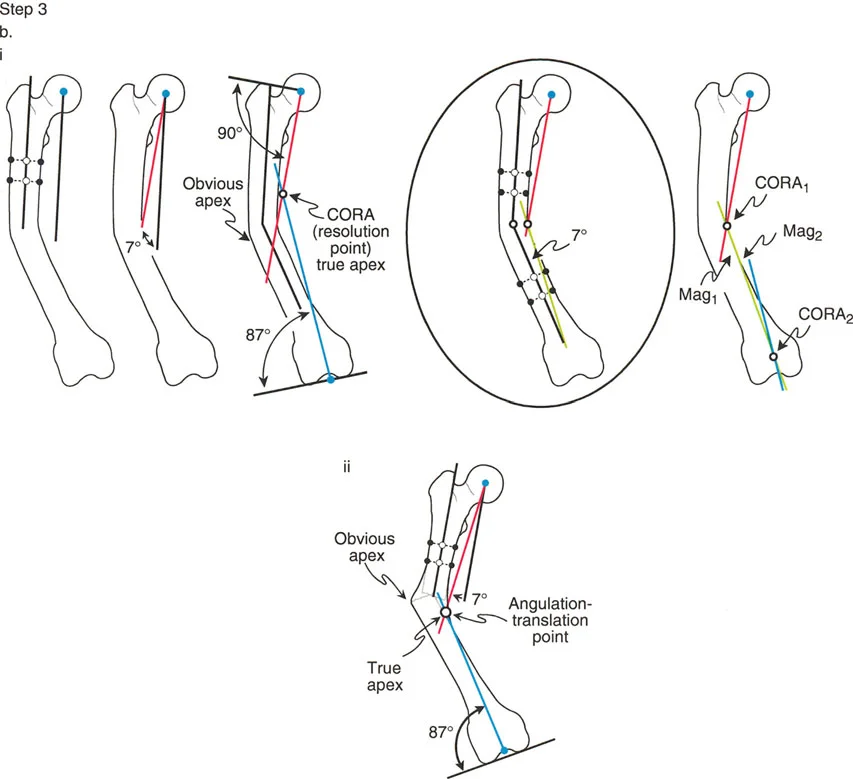
Step 4 Locate the CORA and Determine Magnitude
The point where the proximal mechanical axis line and the distal mechanical axis line intersect is the Center of Rotation of Angulation. The angle formed by this intersection is the magnitude of the deformity. By bisecting this angle, you establish the transverse bisector line, which dictates the optimal level for the femoral osteotomy according to Paley Rule 1 or Rule 2.
Managing Complex Multiapical Deformities
Not all deformities are simple uniapical bends. Severe trauma, metabolic bone diseases like rickets, or congenital conditions like osteogenesis imperfecta often present with multiapical deformities. In these cases, the bone has multiple bends, and a single osteotomy will not restore the mechanical axis without causing severe, unacceptable translation.
When planning for a multiapical deformity, the surgeon must isolate the bone into three or more segments.
1. Draw the proximal mechanical axis referenced off the proximal joint.
2. Draw the distal mechanical axis referenced off the distal joint.
3. Draw an anatomic mid diaphyseal line through the middle, intercalary segment of the bone.
This process will yield two distinct intersection points. The proximal mechanical axis will intersect the mid diaphyseal line creating the proximal Center of Rotation of Angulation. The distal mechanical axis will intersect the mid diaphyseal line creating the distal Center of Rotation of Angulation. The surgeon must then plan two separate osteotomies, applying Paley Osteotomy Rules to each site individually. Modern hexapod circular fixators are particularly adept at managing these complex, multi level corrections simultaneously.
Joint Line Convergence Angle and Soft Tissue Considerations
While bone deformity is the primary focus of axis planning, orthopedic surgeons must never ignore the soft tissues. The Joint Line Convergence Angle is the critical metric for evaluating ligamentous contributions to frontal plane malalignment.
The Joint Line Convergence Angle is measured by drawing a line across the distal femoral condyles and a line across the proximal tibial plateau. In a normal knee, these lines are nearly parallel, with a normal Joint Line Convergence Angle ranging from 0 to 2 degrees.
If a patient presents with a severe varus Mechanical Axis Deviation, the surgeon must evaluate the Joint Line Convergence Angle on a standing radiograph. If the Joint Line Convergence Angle is widened laterally to 6 degrees, it indicates significant lateral ligamentous laxity or medial compartment cartilage loss.
Failing to account for an abnormal Joint Line Convergence Angle is a classic pitfall. If a surgeon corrects a bony deformity to a perfect 87 degree MPTA but ignores a 5 degree lateral soft tissue laxity, the patient will still have a varus thrust during the stance phase of gait. In such cases, the surgeon must either perform a soft tissue reconstruction concurrently or slightly overcorrect the bony osteotomy into valgus to compensate for the lateral ligamentous incompetence.
Advanced Surgical Pearls for Frontal Plane Correction
Mastering the theory of the Center of Rotation of Angulation is only half the battle. Executing the plan in the operating room requires meticulous attention to detail. Below are high yield clinical pearls for the deformity surgeon.
- Radiographic Positioning is Critical: A malrotated radiograph renders all angle measurements useless. Ensure the patella is facing perfectly forward for the anteroposterior standing radiograph. If the patient has a severe rotational deformity, you may need separate AP radiographs of the femur and the tibia to get true orthogonal views of the joints.
- Account for the Sagittal Plane: Frontal plane planning is only one dimension. Always evaluate the lateral radiographs for apex anterior or apex posterior deformities. If a deformity exists in both the frontal and sagittal planes, it is an oblique plane deformity. The true magnitude of an oblique plane deformity is always greater than the magnitude seen on either the AP or lateral film alone.
- Hinge Placement Dictates the Outcome: When performing an opening wedge High Tibial Osteotomy, the lateral cortex acts as the hinge. This hinge is the Axis of Correction of Angulation. Because this hinge is located on the cortex, away from the central Center of Rotation of Angulation, Paley Rule 2 applies. The bone will undergo intentional translation. You must ensure the lateral hinge remains intact to prevent unwanted instability and Rule 3 translation.
- Hardware Selection Matters: Intramedullary nails are excellent for diaphyseal deformities but struggle to control short periarticular segments. Plates and screws offer rigid fixation for periarticular osteotomies but require larger incisions. Hexapod circular fixators offer the ultimate versatility, allowing for gradual correction of the mechanical axis, fine tuning in the postoperative period, and simultaneous correction of length and rotation.
- Respect the Soft Tissues: Acute corrections of large valgus deformities can stretch the common peroneal nerve, leading to foot drop. Acute corrections of large varus deformities can stretch the tibial nerve. Always consider prophylactic nerve decompressions or choose gradual correction with an external fixator when the deformity magnitude exceeds safe limits for acute stretching.
By rigorously applying Dr Paley's principles of the Center of Rotation of Angulation, understanding the intricate relationship between the mechanical and anatomic axes, and respecting the biomechanics of the lower extremity, orthopedic surgeons can predictably and safely restore function to patients with the most challenging limb deformities.
!!! info "Academic Resource & Medical Review"
This academic resource was prepared and medically reviewed by Prof. Dr. Mohammed Hutaif, Consultant Orthopedic & Spine Surgeon. It is formulated specifically for medical students, orthopedic residents, and surgeons preparing for high-stakes board examinations (AAOS, FRCS Tr & Orth, Arab Board).
!!! warning "Disclaimer"
The surgical techniques, classifications, and clinical guidelines presented herein are for educational and academic review purposes only. They are not intended to replace institutional protocols or independent clinical judgment.
You Might Also Like