Biomechanics of Implant Design and Fracture Fixation: A Comprehensive Guide
Key Takeaway
Understanding the biomechanics of implant design and fracture fixation is essential for orthopaedic surgeons. This guide details the material properties of bone, loading modes, and the structural mechanics of pins, wires, and screws. By mastering AO principles, including lag screw techniques and interfragmentary compression, surgeons can optimize construct stability, mitigate implant fatigue, and promote reliable bone healing in complex fracture patterns.
BIOMECHANICS OF BONE AND FRACTURE FIXATION
The foundation of operative orthopaedics rests upon a profound understanding of the biomechanics of implant design and fracture fixation. Evaluating the failure of bone requires a meticulous analysis of the type, magnitude, and rate of load, alongside the intrinsic material and structural properties of the bone itself.
Bone is a highly complex, viscoelastic, and anisotropic material, meaning it exhibits different stress-strain relationships depending on the direction and rate at which stress is applied. Furthermore, cancellous and cortical bone differ significantly due to the porosity and diameter of their respective cross-sections. In vitro studies demonstrate that cortical bone fractures when strain exceeds a mere 2% of its original length. In stark contrast, the highly porous cancellous bone does not fail until strain exceeds 7%, allowing it to absorb significant energy before catastrophic failure.
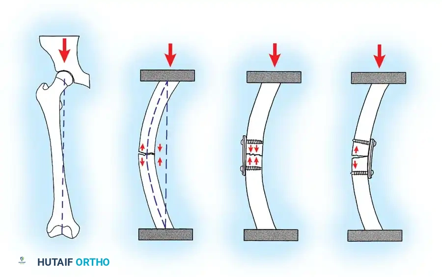
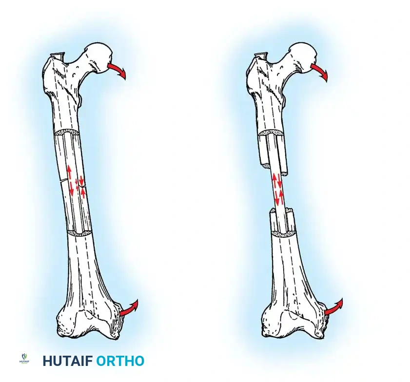
In analyzing fracture patterns, the mode of loading offers critical insight into the mechanism of injury, the energy dissipated, and the likelihood of associated soft-tissue injuries. Loads are classically described as tension, compression, bending, shear, torsion, or a complex combination of these forces. The specific mode of bone failure can accurately predict the extent of the soft-tissue hinge and the inherent stability of the resulting fracture.
Material and Structural Properties of Implants
Devices utilized to stabilize the human skeleton are subjected to relentless loading and deforming forces. While these forces rarely cause acute load-to-failure (as occurs during the initial fracture event), orthopaedic implants are highly susceptible to fatigue failure if the bone does not regenerate rapidly enough to share and eventually accommodate the physiological load.
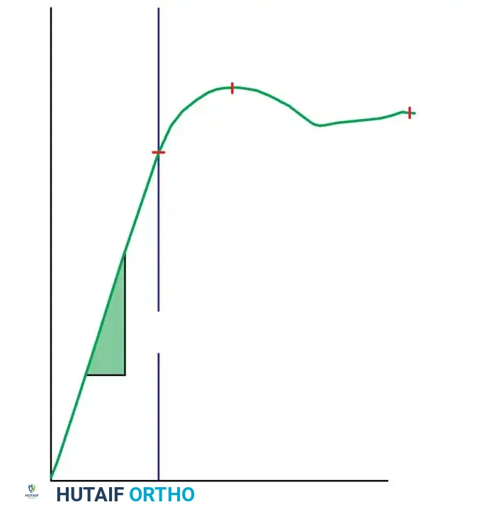
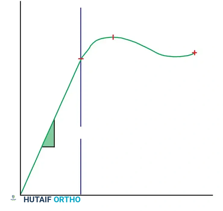
Material properties are graphically expressed by stress-strain curves, whereas structural properties are delineated by load-deformation curves. The structural properties—specifically the area moment of inertia ($I$) and the polar moment of inertia ($J$)—are meticulously modified by engineers to obtain the desired stiffness and strength of implants.
Clinical Pearl: Most orthopaedic implants are designed to function strictly within the elastic deformation phase of the load-deformation curve. Theoretically, there exists an optimal elastic range of micro-motion that favors secondary bone healing (callus formation), but this range differs drastically between direct (primary) and indirect (secondary) forms of bone healing.
When an intramedullary nail, plate and screws, or external fixator is selected, the preoperative plan must rigorously account for the forces the fixation construct will sustain, the fatigue life of the implant, and the compliance of the patient. This biomechanical foresight dictates the postoperative rehabilitation program.
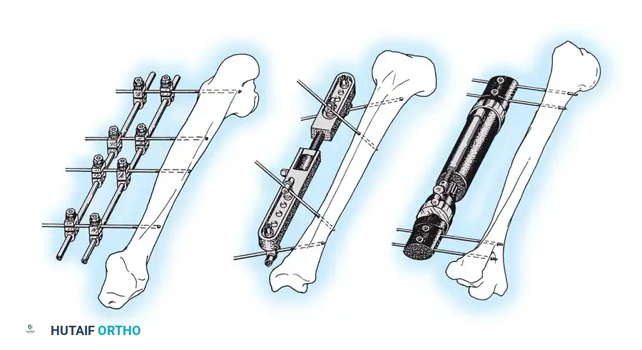
PIN AND WIRE FIXATION
Küntscher originally described the fundamental biomechanical differences between pins, rods, and nails used for fracture fixation:
* Pins: Resist alignment changes only.
* Rods: Resist deviations in alignment and translation.
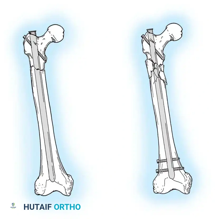
* Nails: Resist changes in alignment, translation, and rotation.
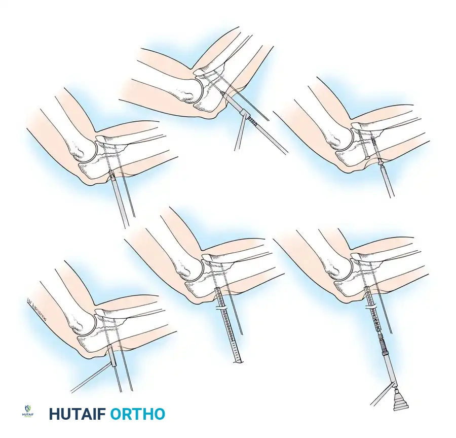
Kirschner wires (K-wires) and Steinmann pins are ubiquitous in orthopaedic surgery, frequently used for both provisional and definitive fracture fixation. Because their resistance to bending loads is inherently poor (due to a small area moment of inertia), if used as definitive fixation, they must be supplemented by external bracing, casting, or external fixation frames.
Insertion Techniques and Thermal Necrosis
If used as definitive fixation, pins are usually inserted percutaneously or via limited open reduction.
Surgical Warning: Thermal necrosis of bone is a primary cause of pin loosening and subsequent infection. To prevent thermal damage to bone and surrounding soft tissues, pins must be inserted slowly using power equipment with frequent stops, or ideally, using a dedicated wire driver.
Smooth wires are generally preferred to facilitate easier removal in the outpatient clinic after fracture healing. Threaded wires provide superior resistance to pull-out forces and hold fractures in place better for temporary fixation; however, the fracture fragments must be manually compressed during wire insertion to avoid distraction. Furthermore, threaded wires carry a higher risk of breakage at the thread-shank junction if the cortical bone is exceptionally hard.
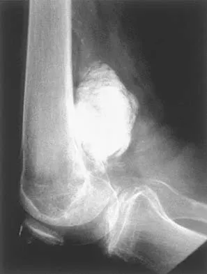
Pin or wire fixation is usually adequate for small fragments in metaphyseal and epiphyseal regions, especially in fractures of the distal radius, foot, and hand (e.g., displaced metacarpal and phalangeal fractures after closed reduction).
Most frequently, pins are inserted under fluoroscopic (image intensifier) control. This minimally invasive approach protects the soft-tissue envelope and periosteal blood supply, theoretically permitting maximal bone regeneration. However, meticulous care must be taken to ensure that tendons, nerves, and neurovascular bundles are not wound around the pin during insertion.
Wire fixation is also utilized alone or in combination with other implants (such as tension band constructs) for definitive fixation of metaphyseal fractures, including the proximal humerus, olecranon, patella, and cervical spine.
Pitfall: Notching or bending the wire sharply at the bone interface should be avoided, as it creates a stress riser that drastically shortens the fatigue life of the implant.
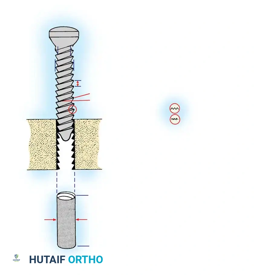
SCREW FIXATION BIOMECHANICS
Screws are complex mechanical tools designed to convert torsional forces into compression. They feature a four-part construction: head, shaft, thread, and tip.
Anatomy of a Bone Screw
- Head: Serves as the attachment point for the screwdriver (hexagonal, cruciate, slotted, star, or Phillips). Crucially, the head serves as the counterforce against which compression generated by the screw acts on the cortical bone or plate.
- Shaft (Shank): The smooth portion of the screw between the head and the threaded portion (present in partially threaded screws).
- Thread: Defined by its root (core) diameter, thread (outside) diameter, pitch (distance between adjacent threads), and lead (distance it advances into the bone with each complete 360-degree turn).
- Tip: Either round (requires pre-tapping) or self-tapping (features a cutting flute or trocar tip).
Biomechanical Principles of Screw Design:
* Pull-out Strength: The root area determines the resistance of the screw to pull-out forces. If pull-out is a clinical concern due to osteoporotic or soft cancellous bone, a screw with a larger thread diameter and wider pitch is preferred.
* Fatigue Resistance: If the bone is strong and implant fatigue is the primary concern, a screw with a wider root (core) diameter provides a higher area moment of inertia, thus resisting bending and fatigue failure.
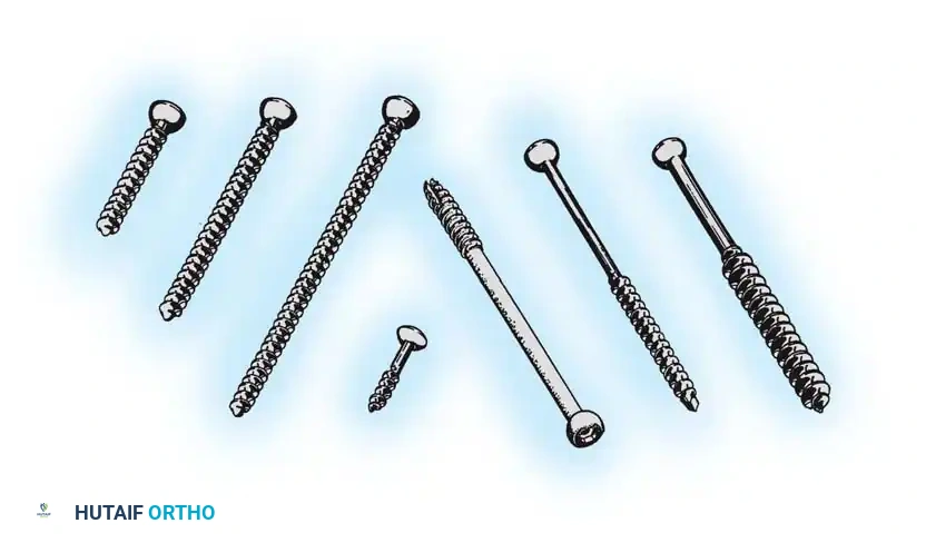
Types of Screws
Machine Screws:
Threaded their entire length, machine screws can be self-tapping or require pre-tapping. They are primarily used to fasten hip compression screw devices to the femoral shaft. The size of the pilot hole is critical: too large results in insecure purchase; too small can cause bone fragmentation or thermal necrosis during insertion.
ASIF Screws:
Designed based on the principles of osteosynthesis developed by the AO/ASIF group, these screws feature threads that are more horizontal than machine screws. Cortical, cancellous, and malleolar designs are available.
Cortical Screws:
Threaded their entire length, available in diameters ranging from 1.5 mm to 4.5 mm. They have a larger core diameter and smaller pitch, optimized for dense diaphyseal bone. They can function as positional screws or as lag screws if the near cortex is intentionally overdrilled (gliding hole).
Cancellous Screws:
Featuring larger thread diameters and wider pitch, these provide superior purchase in soft, metaphyseal, and epiphyseal cancellous bone. They are available in fully threaded or partially threaded designs (e.g., 16 mm or 32 mm thread lengths for 6.5 mm screws).
Locking Screws:
These are self-tapping screws with a threaded conical head that locks directly into a corresponding threaded hole in a locking plate. This creates a fixed-angle construct that does not rely on friction between the plate and bone, making it ideal for osteoporotic bone or complex comminuted fractures.
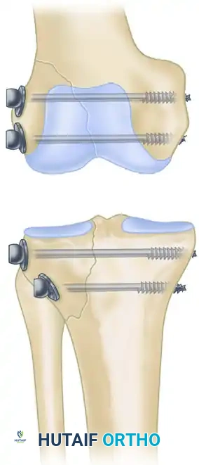
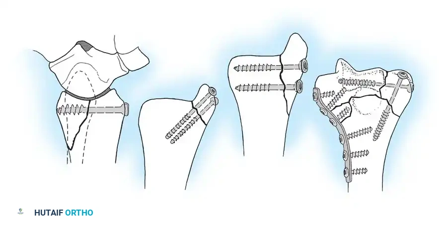
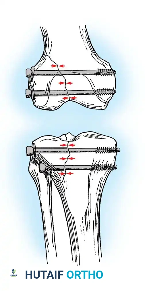
PRINCIPLES OF LAG SCREW TECHNIQUE
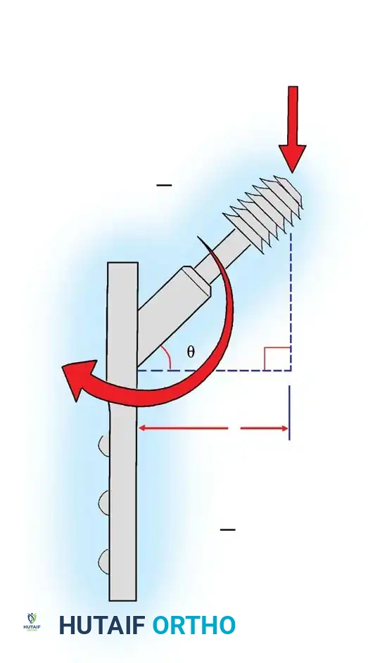
The use of a screw to convert torque forces into static interfragmentary compression across a fracture plane is one of the most valuable techniques in operative orthopaedics.
Its success requires the screw to glide freely through the near bone fragment (gliding hole) and purchase securely only in the opposite cortex (thread hole). As the screw is tightened, the head exerts a load against the near cortex, forcefully compressing the fracture fragments together.
Careful selection of the screw angle relative to the fracture plane is paramount. The lag screw must be directed perpendicular to the fracture plane to achieve maximal compression. If inserted at an incorrect angle, tightening the screw will induce shear forces, causing the fracture fragments to slide and displace.
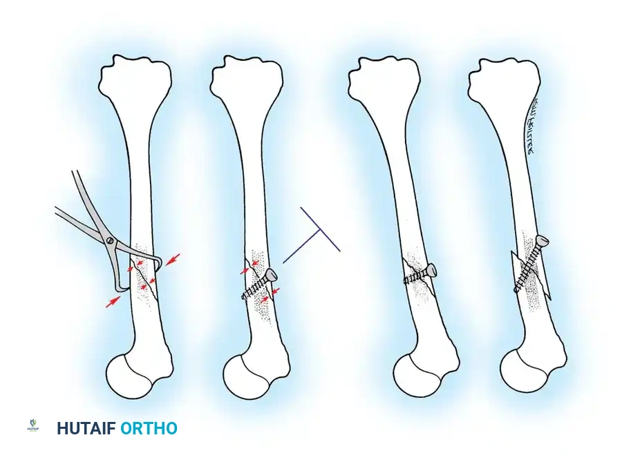
🔪 Surgical Technique 50-3: Interfragmentary Lag Screw Insertion
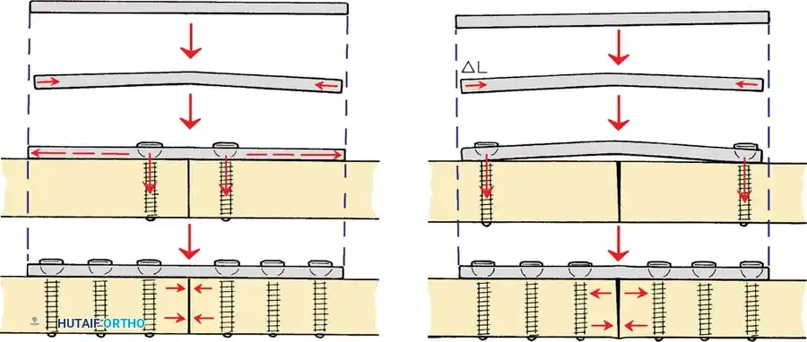
For transverse or short oblique fractures, lag screws must be protected by a neutralization plate. To achieve true interfragmentary compression, follow this standardized AO technique:
- Reduction: Anatomically reduce the fracture and secure the reduction with pointed reduction forceps or provisional Kirschner wires.
- Plan the Trajectory: Plan the position of the screw so that it is inserted in the middle of the fragment, strictly perpendicular to the fracture plane.
- Drill the Gliding Hole: Use a drill bit matching the thread diameter of the screw (e.g., 3.5 mm drill for a 3.5 mm screw) to drill through the near cortex only. This ensures the threads will not purchase in the near fragment.
- Insert the Drill Sleeve: Place a specialized drill sleeve into the gliding hole. This centers the subsequent drill bit and protects the near cortex.
- Drill the Thread Hole: Use a drill bit matching the core diameter of the screw (e.g., 2.5 mm drill for a 3.5 mm screw) to drill through the far cortex.
- Countersink: Use a countersink tool on the near cortex to create a congruent bed for the screw head. This increases the contact area, distributing compressive forces and preventing stress risers or cortical splitting.
- Measure: Use a depth gauge to measure the required screw length. Ensure the hook catches the far cortex. Add 1-2 mm to ensure full thread engagement beyond the far cortex.
- Tap (If applicable): If using non-self-tapping screws, use a tap matching the thread profile to cut threads into the far cortex.
- Insert the Screw: Insert the screw and tighten carefully. As the head engages the countersunk near cortex, interfragmentary compression is achieved.
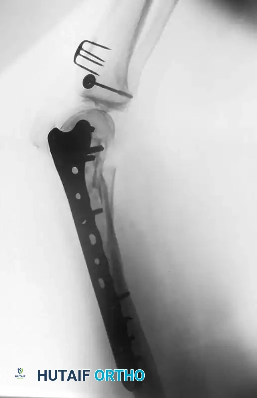
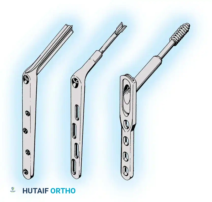
PLATE OSTEOSYNTHESIS BIOMECHANICS
Plates are utilized to bridge fractures, neutralize forces on lag screws, or compress transverse fractures. The biomechanical function of a plate depends entirely on its application.

You Might Also Like