Atlas (C1) Fractures: Advanced Insights into Pathophysiology, Anatomy & Clinical Management

Key Takeaway
Atlas (C1) fractures are upper cervical spine injuries, often from high-energy axial compression. They are classified by systems like Levine's, detailing patterns such as isolated arches or burst (Jefferson) fractures. C1 ring stability, primarily governed by the transverse atlantal ligament (TAL) integrity, is crucial for guiding management and preventing long-term sequelae.
Introduction and Epidemiology
Atlas (C1) fractures represent a significant, albeit relatively uncommon, subset of cervical spine trauma, accounting for approximately 1 to 2 percent of all spinal fractures and 25 percent of cervical spine fractures in the upper cervical region. These injuries are typically the result of high-energy mechanisms, primarily axial compression, often with elements of hyperextension and asymmetric loading of the occipital condyles. This complex loading can lead to a diverse array of fracture patterns within the C1 ring.
A notable characteristic of atlas fractures is their infrequent association with acute neurological injury, a finding often attributed to the relatively wide spinal canal at the C1 level (Steele's Rule of Thirds), which can accommodate displacement without immediate cord compromise. However, this does not diminish the potential for devastating long-term sequelae if instability is unrecognized or inadequately managed. Chronic instability can lead to progressive myelopathy, intractable suboccipital neuralgia, and severe deformity.
Approximately 50 percent of atlas fractures are associated with other cervical spine injuries, particularly those involving the C2 axis. Common concomitant injuries include odontoid fractures (Type II and Type III being most prevalent) and traumatic spondylolisthesis of the axis (Hangman's fracture). The presence of associated injuries necessitates a comprehensive evaluation of the entire cervical and upper thoracic spine to avoid missed diagnoses that could compromise patient outcomes.
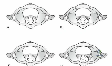
The mechanism of injury dictates the specific fracture morphology. The Levine classification system, a widely recognized scheme, categorizes atlas fractures based on the involved anatomical segments. Isolated bony apophysis fractures are often stable. Isolated posterior arch fractures are typically stable and result from hyperextension. Isolated anterior arch fractures are often stable, resulting from hyperextension or flexion. Comminuted lateral mass fractures indicate higher energy and potential asymmetric loading. Burst fractures, classically known as Jefferson fractures, are characterized by fractures through both the anterior and posterior arches, resulting in splaying of the lateral masses. This pattern is particularly indicative of significant axial load.
The primary determinant of management strategy for atlas fractures is the assessment of C1 ring stability, specifically the integrity of the transverse atlantal ligament (TAL) and, to a lesser extent, the alar ligaments. Instability invariably correlates with TAL insufficiency, which can be diagnosed through direct visualization of bony avulsion on high-resolution computed tomography or ligamentous rupture on magnetic resonance imaging. Indirect assessment is performed by measuring the degree of lateral mass displacement relative to C2. The classic Rule of Spence dictates that a combined lateral mass overhang exceeding 6.9 mm on an open-mouth odontoid radiograph (or coronal CT reconstruction) strongly suggests TAL rupture.
Patients often present with acute neck pain, restricted range of motion, and may describe a subjective feeling of cranial settling or instability. Beyond structural stability, a thorough clinical and radiographic assessment must also evaluate for potential cranial nerve deficits (CN VI to XII), neurapraxia of the suboccipital and greater occipital nerves, and vertebral artery injury, which can manifest as symptoms of basilar insufficiency such as vertigo, blurred vision, or nystagmus.
Surgical Anatomy and Biomechanics
The atlas is a unique, ring-shaped vertebra devoid of a vertebral body and spinous process, designed to articulate with the occipital condyles superiorly and the axis inferiorly. Its primary function is to support the cranium and facilitate a wide range of head movements, particularly axial rotation.
Osteology of the Atlas
The C1 ring comprises an anterior arch, a posterior arch, and two robust lateral masses. The anterior arch forms approximately one-fifth of the ring, featuring an anterior tubercle for the attachment of the longus colli muscles and a posterior articular facet (fovea dentis) for articulation with the odontoid process of C2. The posterior arch forms about two-fifths of the ring, housing the vertebral artery grooves (sulcus arteriosus) on its superior surface just posterior to the lateral masses. It terminates in a posterior tubercle, which serves as a vestigial spinous process and attachment point for the ligamentum nuchae and rectus capitis posterior minor.
The lateral masses are wedge-shaped, being thicker laterally than medially, which contributes to the lateral displacement seen in axial loading injuries. The superior articular facets are concave and kidney-shaped to accommodate the convex occipital condyles, allowing for flexion and extension. The inferior articular facets are relatively flat and circular, articulating with the superior facets of C2 to facilitate extensive axial rotation.
Ligamentous Anatomy
The stability of the atlantoaxial complex is highly dependent on its intricate ligamentous restraints. The transverse atlantal ligament is the primary stabilizer, preventing anterior translation of C1 over C2. It spans the medial tubercles of the C1 lateral masses, securing the dens against the anterior arch. The TAL is a thick, unyielding band; biomechanical studies indicate it can withstand up to 350 Newtons of force before failure.
Secondary stabilizers include the alar ligaments, which originate from the posterolateral aspect of the upper dens and attach to the medial aspect of the occipital condyles, limiting axial rotation and lateral bending. The apical ligament, tectorial membrane (the cephalad continuation of the posterior longitudinal ligament), and the vertical bands of the cruciform ligament provide additional, albeit less critical, restraint against excessive translation and distraction.

Vascular and Neural Considerations
The vertebral artery (V3 segment) ascends through the transverse foramen of C1, courses posteriorly and medially over the superior surface of the posterior arch in the vertebral groove, and pierces the posterior atlanto-occipital membrane to enter the foramen magnum. The distance from the midline to the medial edge of the vertebral artery groove is highly variable but generally ranges from 12 to 18 mm. Surgical dissection on the superior aspect of the C1 posterior arch must remain strictly medial to this zone to avoid catastrophic iatrogenic vertebral artery injury. Additionally, the presence of a ponticulus posticus (arcuate foramen), an ossified bridge over the vertebral artery groove present in up to 15 percent of the population, must be identified preoperatively via CT to avoid inadvertent arterial injury during screw placement.
The C1 nerve root (suboccipital nerve) exits between the occiput and the posterior arch of C1, supplying the suboccipital musculature. The C2 nerve root exits between the posterior arches of C1 and C2, dividing into a small anterior ramus and a large posterior ramus, which continues as the greater occipital nerve. Management of the C2 nerve root during posterior C1-C2 fusion remains a topic of debate, with some surgeons advocating for preservation to avoid postoperative numbness, while others prefer transection to ensure excellent visualization of the C1-C2 joint and minimize postoperative neuropathic pain.
Biomechanical Principles
The occipitocervical junction is the most mobile segment of the human spine. The atlanto-occipital joint is responsible for approximately 50 percent of total cervical flexion and extension (roughly 25 degrees). The atlantoaxial joint is responsible for 50 percent of total cervical axial rotation (roughly 40 to 45 degrees in each direction). A Jefferson burst fracture disrupts the integrity of the C1 ring, decoupling the lateral masses from the anterior and posterior arches. When the TAL is ruptured, the lateral masses splay outward under the axial load of the cranium, leading to loss of occipitocervical height, cranial settling, and severe atlantoaxial instability.
Indications and Contraindications
The decision-making process for managing atlas fractures hinges on the morphological classification of the fracture, the integrity of the TAL, and the presence of associated cervical spine injuries. Dickman's classification of TAL injuries is critical here. Type I injuries involve intrasubstance tears of the ligament, which have a very poor healing potential with conservative management. Type II injuries involve bony avulsion fractures at the insertion site on the C1 lateral mass, which have a much higher rate of union with rigid immobilization.
| Management Strategy | Indications | Contraindications |
|---|---|---|
| Non Operative Hard Collar | Isolated anterior or posterior arch fractures; Non-displaced lateral mass fractures; Intact TAL (Spence rule < 6.9mm). | TAL rupture (Dickman Type I); Severe lateral mass displacement; Unstable concomitant C2 fractures. |
| Non Operative Halo Vest | Bony avulsion of TAL (Dickman Type II); Moderately displaced Jefferson fractures with reducible lateral masses. | Polytrauma precluding halo use; Severe pulmonary disease; Skull fractures; Patient non-compliance. |
| Posterior C1 C2 Fusion | Dickman Type I TAL rupture; Irreducible lateral mass splaying > 7mm; Chronic instability/nonunion; Concomitant unstable odontoid fracture. | Active local infection; Destruction of C1/C2 posterior elements precluding fixation (requires extension to Occiput/C3). |
| Occipitocervical Fusion | Severe comminution of C1 lateral masses precluding screw purchase; Associated atlanto-occipital dislocation. | Isolated C1 ring fractures where C1 lateral masses are intact and usable for fixation. |
Pre Operative Planning and Patient Positioning
Thorough preoperative planning is paramount to executing a safe and effective upper cervical stabilization. High-resolution computed tomography (CT) with fine cuts (1 mm or less) and multiplanar sagittal and coronal reconstructions is the gold standard for defining fracture morphology, assessing lateral mass displacement, and evaluating the bony anatomy for screw purchase.
A critical component of the preoperative CT evaluation is the assessment of the vertebral artery anatomy. Computed tomography angiography (CTA) is highly recommended to identify anomalous vertebral artery courses, such as a medialized V3 segment, an aberrant fenestrated artery, or the presence of a ponticulus posticus. The dimensions of the C1 lateral mass and C2 pedicle/pars must be measured to ensure they can accommodate a standard 3.5 mm or 4.0 mm diameter screw.
Magnetic resonance imaging (MRI) is indicated to directly evaluate the integrity of the transverse atlantal ligament, the alar ligaments, and the tectorial membrane. MRI is also essential for ruling out occult spinal cord injury, epidural hematoma, or concomitant intervertebral disc herniations that might complicate the surgical approach or reduction maneuvers.
Patient Positioning
The patient is typically positioned prone on a radiolucent Jackson spinal table. The head is secured in a rigid three-pin Mayfield skull clamp. Positioning of the head and neck is a critical step. The neck should be maintained in a neutral position to prevent excessive flexion or extension, which could exacerbate spinal cord compression in the setting of instability. A military tuck position (slight capital flexion with lower cervical extension) can help open the posterior interlaminar spaces, but extreme care must be taken not to over-distract or subluxate the unstable C1-C2 joint.
Reverse Trendelenburg positioning is frequently utilized to decrease venous engorgement in the epidural venous plexus, thereby minimizing intraoperative blood loss. The shoulders are taped down using heavy adhesive tape to pull the clavicles inferiorly, maximizing lateral fluoroscopic visualization of the lower cervical spine, although this is less critical for isolated C1-C2 pathology than for lower cervical procedures. Intraoperative neuromonitoring, including somatosensory evoked potentials (SSEPs) and motor evoked potentials (MEPs), is standard practice to detect any iatrogenic neurologic compromise during positioning and subsequent surgical steps.
Detailed Surgical Approach and Technique
The modern workhorse for surgical stabilization of unstable atlas fractures is the posterior C1-C2 polyaxial screw and rod construct, popularized by Harms and Melcher. This technique provides superior biomechanical stability compared to older wiring techniques and avoids the anatomical constraints of transarticular screws.
Surgical Exposure
A standard posterior midline cervical incision is made extending from the external occipital protuberance to the spinous process of C3. The avascular midline ligamentum nuchae is divided using electrocautery. Subperiosteal dissection is performed to expose the spinous process and laminae of C2. Dissection then proceeds superiorly to expose the posterior arch of C1.
Strict adherence to anatomical boundaries is mandatory. Dissection on the superior aspect of the C1 posterior arch must not extend laterally beyond 12 to 15 mm from the midline to avoid injuring the vertebral artery in the sulcus arteriosus. The inferior border of the C1 posterior arch is dissected to identify the C2 nerve root and the extensive epidural venous plexus surrounding it.
Management of the C2 Nerve Root and Venous Plexus
The C2 nerve root traverses the posterior aspect of the C1-C2 joint. To achieve adequate visualization for C1 lateral mass screw placement and joint decortication, the nerve root must be managed. The venous plexus surrounding the nerve root is often robust and can be a source of torrential bleeding. Meticulous hemostasis is achieved using bipolar electrocautery, hemostatic matrix (e.g., Floseal), and gentle packing with cottonoid patties.
Surgeons may choose to retract the C2 nerve root inferiorly or superiorly. Alternatively, the nerve root can be ligated and transected. Transection provides unparalleled visualization of the C1-C2 joint articulation and creates a large bed for bone grafting, though it results in predictable postoperative numbness in the distribution of the greater occipital nerve.
C1 Lateral Mass Screw Placement
The entry point for the C1 lateral mass screw is at the junction of the posterior arch and the midpoint of the C1 lateral mass. If the posterior arch is thick, a high-speed burr can be used to create a starting hole or resect the inferior portion of the arch to facilitate a straight trajectory.
The trajectory is typically 10 to 15 degrees medial to direct the screw toward the thickest portion of the lateral mass and away from the vertebral artery laterally. The sagittal trajectory is approximately 5 to 10 degrees cephalad, aiming toward the anterior tubercle of C1, keeping the screw parallel to the superior articular surface. A 3.0 mm drill is advanced under fluoroscopic guidance to a depth of 26 to 30 mm, ensuring the anterior cortex is engaged for bicortical purchase, which significantly increases pullout strength. The tract is palpated with a ball-tipped probe, tapped if cortical bone is dense, and a 3.5 mm polyaxial screw is inserted.
C2 Fixation Options
Fixation at C2 can be achieved via pedicle screws, pars screws, or translaminar screws, depending on patient anatomy and surgeon preference.
* C2 Pedicle Screws: Offer the highest biomechanical pullout strength. The entry point is in the cranial and lateral quadrant of the C2 isthmus. The trajectory is 20 to 25 degrees medial and 15 to 20 degrees cephalad.
* C2 Pars Screws: Utilized when the pedicle is too narrow or the vertebral artery has an anomalous medial course. The entry point is slightly more medial and cranial than the pedicle screw. The trajectory is parallel to the C2 pars interarticularis, typically 10 degrees medial and 20 degrees cephalad.
* C2 Translaminar Screws: An excellent salvage option or primary choice when the vertebral artery anatomy precludes pars or pedicle screws. Screws are placed in a crossed trajectory through the base of the C2 spinous process into the contralateral lamina.
Reduction and Arthrodesis
Once screws are bilaterally placed in C1 and C2, appropriately contoured titanium or cobalt-chrome rods are secured into the polyaxial heads. If the C1 lateral masses are splayed, reduction can be achieved by applying compression across the construct before final tightening.
Arthrodesis is the ultimate goal of the procedure. The posterior aspect of the C1-C2 joint is aggressively decorticated using a high-speed burr or curettes. The posterior arch of C1 and the laminae and spinous process of C2 are also decorticated. Autologous bone graft, typically harvested from the iliac crest or local bone drillings, is packed tightly into the decorticated joint spaces and laid over the posterior elements. Structural allograft or demineralized bone matrix can be used as an adjunct.
Complications and Management
Surgical management of atlas fractures carries distinct risks due to the complex neurovascular anatomy of the upper cervical spine. Meticulous technique and preoperative planning are required to minimize these complications.
| Complication | Estimated Incidence | Prevention and Salvage Strategies |
|---|---|---|
| Vertebral Artery Injury | 1% to 4% | Prevention: Pre-op CTA, strict adherence to midline dissection (stay <12mm lateral on C1 superior arch), fluoroscopic guidance. Salvage: Immediate tamponade, direct repair (rarely feasible), endovascular embolization. Avoid contralateral screw placement to prevent bilateral occlusion. |
| C2 Neuralgia / Numbness | 10% to 20% | Prevention: Careful retraction of the C2 nerve root, avoiding over-distraction of the joint. Salvage: If nerve is transected, numbness is expected. Neuropathic pain can be managed with gabapentinoids or local nerve blocks. |
| Venous Epidural Bleeding | 15% to 30% | Prevention: Reverse Trendelenburg positioning, avoiding excessive abdominal pressure. Salvage: Bipolar electrocautery, hemostatic matrix (Floseal/Surgiflo), gentle packing, patience. |
| Hardware Failure / Pullout | 2% to 5% | Prevention: Bicortical C1 screw purchase, optimizing C2 trajectory, adequate bone quality assessment. Salvage: Revision to larger diameter rescue screws, extension of fusion construct to Occiput or C3. |
| Pseudarthrosis (Nonunion) | 2% to 6% | Prevention: Aggressive joint decortication, use of high-quality autograft, rigid construct fixation. Salvage: Revision surgery with re-grafting, possible anterior transarticular screw placement, or extension of fusion. |
| Cranial Settling / Kyphosis | 1% to 3% | Prevention: Anatomical reduction prior to final tightening, avoiding over-compression. Salvage: Revision instrumentation with structural grafting to restore height. |
Post Operative Rehabilitation Protocols
Postoperative management is tailored to the stability of the surgical construct and the quality of the patient's bone. In the setting of a rigid posterior C1-C2 polyaxial screw and rod construct with good bone purchase, patients are typically mobilized on postoperative day one.
Immobilization usually consists of a rigid cervical collar (e.g., Aspen or Miami J collar) worn for 6 to 12 weeks. The collar serves primarily as an adjunct to limit extremes of motion and provide comfort while the soft tissues heal and the bony fusion mass begins to consolidate. Halo vest immobilization is rarely required following rigid internal fixation unless bone quality is exceptionally poor (e.g., severe osteoporosis) or hardware purchase was suboptimal.
Radiographic follow-up is critical. Upright, weight-bearing lateral and anteroposterior cervical radiographs are obtained prior to discharge, and subsequently at 2 weeks, 6 weeks, and 12 weeks postoperatively to monitor for hardware failure, loss of reduction, or progressive deformity.
A fine-cut CT scan of the cervical spine is the definitive modality for assessing arthrodesis and is typically obtained at 6 months postoperatively. Once bridging trabecular bone is visualized across the decorticated C1-C2 joints or posterior elements, the collar can be completely discontinued.
Physical therapy is initiated after clinical and radiographic evidence of early healing (usually around 6 to 8 weeks). Initial therapy focuses on isometric neck strengthening and gentle, active range of motion. Patients must be counseled that they will experience a permanent loss of approximately 50 percent of their cervical axial rotation due to the C1-C2 arthrodesis. Return to high-impact activities or contact sports is generally contraindicated, though return to normal daily activities and low-impact exercise is expected by 6 to 9 months.
Summary of Key Literature and Guidelines
The management of atlas fractures has evolved significantly over the past several decades, driven by critical anatomical studies and biomechanical advancements in spinal instrumentation.
- Spence et al. (1970): Established the "Rule of Spence," a landmark radiographic guideline. The study demonstrated that a combined lateral mass displacement of greater than 6.9 mm on an open-mouth odontoid radiograph correlates with a complete rupture of the transverse atlantal ligament, indicating a highly unstable C1 ring that typically requires surgical stabilization.
- Dickman et al. (1996): Provided the definitive classification system for transverse atlantal ligament injuries using MRI. They differentiated between intrasubstance tears (Type I), which rarely heal with rigid immobilization and require surgery, and bony avulsion fractures (Type II), which have a 74% success rate with halo vest immobilization.
- Harms and Melcher (2001): Revolutionized the surgical management of atlantoaxial instability by introducing the technique of posterior C1 lateral mass and C2 pedicle screw fixation. This polyaxial screw-rod construct provided superior biomechanical rigidity compared to traditional Brooks or Gallie wiring techniques and eliminated the need for routine halo immobilization postoperatively.
- AANS/CNS Joint Section Guidelines: The American Association of Neurological Surgeons and the Congress of Neurological Surgeons provide evidence-based guidelines for the management of acute cervical spine trauma. Current guidelines strongly recommend MRI evaluation for suspected ligamentous injury in C1 fractures and advocate for surgical stabilization in the setting of documented TAL rupture with C1 ring instability. Non-operative management with external orthosis remains the standard of care for isolated, stable arch fractures with an intact TAL.
Clinical & Radiographic Imaging


