Introduction & Epidemiology
Atlas (C1) fractures represent a significant, albeit relatively uncommon, subset of cervical spine trauma, accounting for approximately 1-2% of all spinal fractures and 25% of cervical spine fractures in the upper cervical region. These injuries are typically the result of high-energy mechanisms, primarily axial compression, often with elements of hyperextension and asymmetric loading of the occipital condyles. This complex loading can lead to a diverse array of fracture patterns within the C1 ring.
A notable characteristic of atlas fractures is their infrequent association with acute neurological injury, a finding often attributed to the relatively wide spinal canal at the C1 level, which can accommodate displacement without immediate cord compromise. However, this does not diminish the potential for devastating long-term sequelae if instability is unrecognized or inadequately managed.
Approximately 50% of atlas fractures are associated with other cervical spine injuries, particularly those involving the C2 axis. Common concomitant injuries include odontoid fractures (Type II and Type III being most prevalent) and traumatic spondylolisthesis of the axis (Hangman's fracture). The presence of associated injuries necessitates a comprehensive evaluation of the entire cervical and upper thoracic spine to avoid missed diagnoses that could compromise patient outcomes.
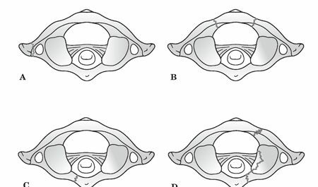
The mechanism of injury, axial compression with varying degrees of hyperextension and asymmetric loading, dictates the specific fracture morphology. The Levine classification system, a widely recognized scheme, categorizes atlas fractures based on the involved anatomical segments:
*
Isolated bony apophysis fracture:
Often stable.
*
Isolated posterior arch fracture:
Typically stable, resulting from hyperextension.
*
Isolated anterior arch fracture:
Often stable, resulting from hyperextension or flexion.
*
Comminuted lateral mass fracture:
Indicates higher energy.
*
Burst fracture (Jefferson fracture):
Characterized by fractures through both the anterior and posterior arches, resulting in splaying of the lateral masses. This pattern is particularly indicative of significant axial load.

The primary determinant of management strategy for atlas fractures is the assessment of C1 ring stability, specifically the integrity of the transverse atlantal ligament (TAL) and, to a lesser extent, the alar ligaments. Instability invariably correlates with TAL insufficiency, which can be diagnosed through direct visualization of bony avulsion on CT or ligamentous rupture on MRI, or indirectly by measuring the degree of lateral mass displacement relative to C2 (Spence's rule). Patients often present with acute neck pain and may describe a subjective feeling of "instability." Beyond structural stability, a thorough clinical and radiographic assessment must also evaluate for potential cranial nerve deficits (CN VI to XII), neurapraxia of the suboccipital and greater occipital nerves, and vertebral artery injury, which can manifest as symptoms of basilar insufficiency such as vertigo, blurred vision, or nystagmus.
Surgical Anatomy & Biomechanics
The atlas (C1) is a unique, ring-shaped vertebra devoid of a body and spinous process, designed to articulate with the occipital condyles superiorly and the axis (C2) inferiorly. Its primary function is to support the skull and facilitate a wide range of head movements, particularly rotation.
The C1 ring comprises an anterior arch, a posterior arch, and two robust lateral masses.
*
Anterior Arch:
Forms about one-fifth of the ring, featuring an anterior tubercle and a posterior facet for articulation with the odontoid process (dens) of C2.
*
Posterior Arch:
Forms about two-fifths of the ring, housing the vertebral artery grooves posteriorly and terminating in a posterior tubercle (vestigial spinous process).
*
Lateral Masses:
These are the strongest parts of the atlas, situated between the anterior and posterior arches. They bear the weight of the head and articulate with the occipital condyles superiorly and the superior articular facets of C2 inferiorly. The superior articular facets are reniform and concave, while the inferior facets are nearly flat and circular. The transverse foramina, transmitting the vertebral arteries, are located within the lateral masses. The medial aspect of the lateral mass is where the tubercle for the transverse atlantal ligament attachment is found.
Ligamentous structures are paramount for C1-C2 stability:
*
Transverse Atlantal Ligament (TAL):
This is the single most critical ligament for C1-C2 stability. It traverses behind the odontoid process, connecting the medial tubercles on the lateral masses of C1. Its primary role is to prevent anterior displacement of C1 on C2 and posterior subluxation of the odontoid into the spinal canal. Disruption of the TAL, whether by direct tear or avulsion of its bony attachments, is the hallmark of C1 instability.
*
Alar Ligaments:
Paired ligaments extending from the tip of the odontoid process to the medial aspects of the occipital condyles. They primarily limit axial rotation and lateral bending of the head and C1 relative to C2.
*
Apical Ligament:
A small, fibrous band connecting the apex of the odontoid to the anterior margin of the foramen magnum.
*
Tectorial Membrane:
The cephalad continuation of the posterior longitudinal ligament, covering the anterior aspect of the spinal canal and the cruciform ligament (which includes the TAL). It provides secondary stability.
The biomechanics of atlas fractures primarily revolve around axial compression. A pure axial load typically results in a burst fracture (Jefferson fracture) where the occipital condyles are driven downwards, forcing the lateral masses outwards. This splaying often leads to disruption of the C1 ring at its weakest points, typically anterior and posterior arches. The key determinant of stability in a Jefferson fracture is the integrity of the TAL. Spence's rule dictates that if the sum of the overhangs of the C1 lateral masses relative to C2 on an open-mouth odontoid view exceeds 6.9 mm, TAL rupture is highly probable, indicating mechanical instability.
Associated mechanisms, such as hyperextension or lateral bending, can produce isolated anterior or posterior arch fractures, or unilateral lateral mass fractures. Rotational forces, often combined with axial load, can lead to asymmetric fracture patterns. The rare complete disruption of the C1 ring with associated cranio-cervical dislocation carries a high mortality rate.
The close proximity of neurovascular structures to the C1 ring is crucial. The vertebral arteries ascend through the transverse foramina of C6 to C1, then make a sharp posteromedial turn within the sulcus arteriosus of the C1 posterior arch before entering the foramen magnum. Fractures, particularly those involving the lateral masses or posterior arch, can directly injure or cause vasospasm of the vertebral artery. The suboccipital nerve (C1 posterior ramus) exits between the posterior arch of C1 and the occiput, while the greater occipital nerve (C2 posterior ramus) lies superficial to the C2 spinous process. Cranial nerves VI to XII are vulnerable in high cervical trauma, although direct nerve injury from C1 fractures is less common than from C2 or more caudal injuries.
Indications & Contraindications
Management of atlas fractures spans a spectrum from conservative immobilization to complex surgical reconstruction. The decision-making process is guided primarily by the assessment of stability, the presence of neurological deficits, associated injuries, and patient comorbidities.
Indications for Non-Operative Management
Non-operative treatment is typically reserved for stable atlas fractures without significant ligamentous disruption or neurological compromise. The cornerstone of conservative management is external immobilization, usually with a rigid cervical collar or a halo vest.
-
Stable C1 fractures:
- Isolated anterior or posterior arch fractures without significant displacement.
- Jefferson fractures with intact transverse atlantal ligament (TAL). This is often inferred if the sum of lateral mass displacement on plain radiographs (Spence's rule) is less than 6.9 mm. MRI can directly confirm TAL integrity.
- Avulsion fractures of the C1 posterior tubercle or isolated bony apophysis fractures.
- No neurological deficit: Patients must be neurologically intact.
- Acceptable alignment: No significant malalignment or angulation.
- Good patient compliance: Essential for successful non-operative outcomes, especially with halo vest application.
Immobilization duration typically ranges from 6 to 12 weeks, followed by gradual weaning and initiation of rehabilitation. Regular radiographic follow-up is necessary to monitor fracture healing and maintain alignment.
Indications for Operative Management
Surgical intervention is indicated when there is evidence of instability, irreducible displacement, significant neurological compromise, or in the presence of associated injuries that necessitate stabilization.
-
Instability due to Transverse Atlantal Ligament (TAL) disruption:
- Direct evidence of TAL rupture on MRI.
- Indirect evidence of TAL disruption, such as a sum of lateral mass displacement (Spence's rule) greater than 6.9 mm (some literature suggests 7mm or 8.2mm, but 6.9mm is widely cited as the threshold for TAL failure).
- Bony avulsion of the TAL attachment on CT scan, indicating an osseous TAL injury.
- Irreducible C1 fractures with significant displacement: Even in the absence of complete TAL rupture, gross displacement or persistent subluxation under traction may warrant surgical stabilization.
- Associated unstable cervical spine fractures: Particularly unstable odontoid fractures (Type II or III), Hangman's fractures, or lower cervical spine injuries requiring surgical fusion. In these scenarios, C1 stabilization may be performed concurrently as part of a longer construct or as a C1-C2 fusion.
- Progressive neurological deficit: Although rare for isolated C1 fractures, any new or worsening neurological deficit mandates urgent surgical decompression and stabilization. This can include cranial nerve palsies or upper cervical myelopathy.
- Vertebral artery injury requiring stabilization: While not a direct indication for C1 fixation, if the fracture pattern directly compromises the vertebral artery and stability is compromised, it may influence the choice and extent of stabilization.
- Non-union or symptomatic malunion: For patients with persistent pain or instability following conservative management.
Contraindications for Operative Management
Absolute contraindications for C1 fracture surgery are rare and primarily revolve around the patient's overall medical status.
- Severe medical comorbidities: Patients with unstable medical conditions that preclude safe anesthesia and surgical intervention.
- Active systemic or local infection: Surgical hardware placement in the presence of infection carries a high risk of implant failure and osteomyelitis.
- Non-displaced, stable fractures: These are appropriately managed non-operatively.
- Lack of surgical expertise or resources: Complex upper cervical spine surgery requires specialized training, equipment, and a multidisciplinary team.
Table 1: Operative vs. Non-Operative Indications for Atlas Fractures
| Indication Category | Non-Operative Management | Operative Management |
|---|---|---|
| Stability Assessment | Stable fracture patterns (isolated ant/post arch, stable Jefferson) | Unstable fracture patterns (TAL rupture/bony avulsion, Spence's > 6.9mm) |
| Ligamentous Integrity | Intact Transverse Atlantal Ligament (TAL) on MRI/CT | Ruptured TAL or bony avulsion of TAL |
| Lateral Mass Displacement | Sum of lateral mass displacement < 6.9 mm (Spence's rule) | Sum of lateral mass displacement > 6.9 mm (Spence's rule) |
| Neurological Status | No neurological deficit | Progressive or new neurological deficit, cranial nerve palsies |
| Associated Injuries | No unstable associated cervical spine fractures | Unstable associated C2 or lower cervical spine fractures requiring fixation |
| Fracture Configuration | Isolated non-displaced fractures | Irreducible fractures with significant displacement, symptomatic non-union |
| Vertebral Artery | No compromise, or stable compromise managed non-surgically | Direct compromise by unstable fracture, or requiring stabilization for other reasons |
Pre-Operative Planning & Patient Positioning
Thorough pre-operative planning is crucial for successful outcomes in atlas fracture surgery, particularly given the complex anatomy and vital neurovascular structures in the C1-C2 region.
Pre-Operative Planning
-
Comprehensive Imaging Review:
- Plain Radiographs: Anteroposterior, lateral, and open-mouth odontoid views. These provide initial assessment of alignment and C1-C2 relationships, including Spence's rule for lateral mass displacement.
- Computed Tomography (CT) Scan: The gold standard for bony detail. Fine-cut (≤1mm) axial, sagittal, and coronal reconstructions are essential. This allows for detailed evaluation of fracture patterns, bony avulsions of ligament attachments (e.g., TAL), degree of lateral mass comminution, and assessment of the transverse foramen for vertebral artery impingement. 3D reconstructions are highly beneficial for visualizing the C1 ring architecture and planning screw trajectories.
- Magnetic Resonance Imaging (MRI): Crucial for evaluating soft tissue structures, especially ligamentous integrity (TAL, alar ligaments, tectorial membrane), and assessing for spinal cord or nerve root compression, edema, or hemorrhage. It also aids in identifying any epidural hematoma.
- CT Angiography (CTA) or MR Angiography (MRA): Indicated if there is suspicion of vertebral artery injury (e.g., fracture line extending into or near the transverse foramen, signs of basilar insufficiency). This helps identify vessel occlusion, dissection, or pseudoaneurysm formation, which directly impacts surgical planning and screw trajectory. Pre-operative angiography with balloon occlusion testing may be considered for high-risk cases to assess collateral flow.
- Assessment of Associated Injuries: Meticulous examination of the entire cervical spine for concomitant fractures, particularly at C2 (odontoid, Hangman's), is mandatory. The presence of other unstable injuries will dictate the extent of fusion.
- Neurological Assessment: A detailed neurological examination should be documented pre-operatively, including cranial nerves, motor, sensory, and reflex functions, to establish a baseline.
-
Surgical Strategy & Instrumentation:
- Approach Selection: Posterior approach is most common for C1 stabilization or C1-C2 fusion. Anterior approaches (transoral, anterior retropharyngeal) are rarely used for C1 fractures but may be considered for irreducible anterior arch displacement or non-union.
- Fixation Technique: Options include C1 lateral mass screws, C1 posterior arch screws/wiring (less common), and C1-C2 fusion constructs (e.g., Goel-Harms C1 lateral mass-C2 pedicle/pars screws, Magerl C1-C2 transarticular screws). The choice depends on fracture morphology, TAL integrity, and associated C2 injuries.
- Screw Trajectory Planning: Based on CT scans, precise entry points and trajectories for C1 lateral mass screws and C2 pedicle/pars screws must be planned to avoid the vertebral artery, spinal cord, and cranial nerves.
- Bone Grafting: Autograft (e.g., iliac crest) or allograft options should be considered for fusion procedures.
- Patient Optimization: Address any medical comorbidities, optimize nutrition, and ensure appropriate antibiotic prophylaxis.
Patient Positioning
The most common approach for atlas fracture stabilization is posterior.
- General Anesthesia: Administered with fiberoptic intubation or awake intubation for patients with unstable cervical spines, minimizing neck manipulation.
-
Prone Position:
The patient is carefully turned prone on a radiolucent operating table.
- Head Support: The head is typically secured in a Mayfield skull clamp or a horseshoe headrest. For unstable injuries, gentle axial traction (e.g., 5-10 lbs) via skull tongs may be applied prior to and during positioning to maintain alignment, especially if pre-operative traction was used. The skull clamp provides rigid fixation, which is critical for precise screw placement and intraoperative imaging.
- Neck Position: The neck should be positioned in neutral to slight flexion to facilitate posterior exposure and reduction maneuvers. Excessive flexion can compromise venous drainage and potentially increase epidural bleeding.
- Chest and Pelvic Rolls: Placed to elevate the chest and pelvis, allowing the abdomen to hang free. This reduces intra-abdominal pressure, minimizes epidural venous engorgement, and decreases intraoperative bleeding.
- Padding: All pressure points (eyes, ears, shoulders, elbows, knees, ankles) are meticulously padded to prevent pressure ulcers or nerve palsies.
-
Intraoperative Imaging:
- Fluoroscopy: Essential for confirming levels, guiding screw placement, and assessing alignment. Anteroposterior and lateral fluoroscopic views are routinely used. Oblique views may be helpful for specific screw trajectories.
- Navigation: Increasingly, intraoperative navigation systems (e.g., O-arm, StealthStation) are employed, especially for complex upper cervical cases. These systems provide real-time 3D imaging and guidance, enhancing accuracy and safety of screw placement, particularly for C1 lateral mass and C2 pedicle/pars screws, significantly reducing the risk of vertebral artery or spinal cord injury.

Detailed Surgical Approach / Technique
The primary surgical goal for unstable atlas fractures is to restore stability, decompress neural elements if compromised, and facilitate fusion. The most common and versatile approach for C1 stabilization is posterior, often involving a C1-C2 fusion.
Posterior C1-C2 Fusion (Goel-Harms Technique)
This technique involves the placement of C1 lateral mass screws and C2 pedicle or pars screws, connected by rods. It provides robust three-column stabilization and high fusion rates.
-
Incision and Exposure:
- A midline posterior incision is made from the external occipital protuberance to the C3/C4 spinous process level.
- The ligamentum nuchae is sharply incised.
- Subperiosteal dissection is performed bilaterally, carefully elevating the paraspinal muscles (trapezius, splenius capitis, semispinalis capitis) from the occiput, C1 posterior arch, C2 spinous process and lamina, and extending caudally to expose C3 lamina.
- Crucial landmarks: Identify the C2 spinous process (typically the first palpable bifid spinous process below the occiput). The C1 posterior arch lies superior to C2. The C1 posterior arch is thin and devoid of a spinous process, making careful dissection important to avoid inadvertent entry into the spinal canal.
- Internervous Planes: While not a true internervous plane in the classical sense, the midline approach separates the semispinalis capitis muscles, minimizing muscle damage. Careful subperiosteal dissection along the posterior elements avoids injury to the greater occipital nerve (medial to the semispinalis capitis at C2) and suboccipital nerve (exiting between C1 and occiput).
- Vertebral Artery Considerations: Particular caution is exercised during dissection superior to the C1 posterior arch, where the vertebral artery courses in its sulcus. Dissection should be limited to the superior aspect of the C1 arch to avoid injury.
-
C1 Lateral Mass Screw Placement:
- Entry Point: The entry point for the C1 lateral mass screw is typically at the junction of the inferior margin of the C1 posterior arch and the medial aspect of the C1 lateral mass, just inferior to the C1 posterior tubercle for the TAL. Some authors advocate for a point slightly superior and lateral on the posterior surface of the lateral mass.
-
Trajectory:
- Medial Angle: The screw is directed approximately 10-15 degrees medially to converge towards the contralateral occipital condyle, aiming to engage the dens and maximize purchase within the thickest part of the lateral mass.
- Cranial Angle: A slight cranial angulation (approximately 0-10 degrees) is generally employed, parallel to the superior articular facet of C1. This trajectory avoids the vertebral artery laterally and inferiorly, and the spinal canal medially.
- Depth: Screw length typically ranges from 24-28 mm. Intraoperative fluoroscopy (lateral and open-mouth odontoid views) or navigation is indispensable to confirm correct trajectory and depth. The screws should not penetrate the anterior cortex of the C1 lateral mass into the C1-C2 joint space.
- Technique: A small pilot hole is created with a high-speed burr. A blunt awl or probe is then used to breach the cortical bone. The trajectory is confirmed with a ball-tip probe. The screw is then carefully inserted.
-
C2 Pedicle/Pars Screw Placement:
- Entry Point (Pedicle Screw): Approximately 2-3 mm superior and medial to the center of the C2-C3 articular facet, or at the junction of the lateral mass and the inferior border of the C2 lamina/pars.
-
Trajectory (Pedicle Screw):
- Medial Angle: Approximately 20-30 degrees convergence to the contralateral C2 pedicle, aiming towards the C2 body.
- Cranial Angle: Approximately 20-30 degrees cranial angulation, parallel to the superior endplate of C2.
- Depth: Screws typically 28-34 mm.
- Entry Point (Pars Interarticularis Screw): At the junction of the pars and the lamina, lateral to the C2 spinous process.
- Trajectory (Pars Interarticularis Screw): Less medial angulation than a pedicle screw (around 10-15 degrees). Similar cranial angulation. This option is safer in cases of narrow C2 pedicles.
- Technique: Similar to C1 screw placement, using a pilot hole, awl, and ball-tip probe for trajectory confirmation. The C2 pedicle houses the C2 nerve root and the vertebral artery. Extreme care and often navigation are required.
-
Reduction and Rod Placement:
- Once C1 lateral mass and C2 pedicle/pars screws are in place, appropriate length contoured rods are selected.
- Reduction: For burst fractures with lateral mass splaying, the C1 lateral masses are reduced medially by gently compressing the C1 screws towards the midline with rod seating and final tightening. This effectively closes the C1 ring and indirectly reduces the C1-C2 articulation.
- Rods are secured to the screws using locking caps or nuts. Compression or distraction maneuvers can be applied as needed to achieve optimal alignment.
-
Bone Grafting:
- Decortication of the posterior arch of C1 and the lamina/spinous process of C2 is performed using a high-speed burr to prepare a bleeding bed for fusion.
- Autogenous bone graft (e.g., local bone harvested during decortication, or supplemental autograft from iliac crest) or allograft is placed over the decorticated surfaces and around the instrumentation to promote arthrodesis.
-
Closure:
- Meticulous hemostasis is achieved.
- Wound is irrigated thoroughly.
- Deep fascia and subcutaneous layers are closed, followed by skin closure. Drains may be utilized.
C1 Posterior Arch Fixation
In very select cases of isolated C1 posterior arch fractures that are unstable but without significant lateral mass splaying or TAL injury, a C1 posterior arch screw or wire may be considered. However, C1 lateral mass screw fixation offers superior biomechanical stability and is generally preferred, often in conjunction with C2 fixation for fusion.
Anterior Approaches (Transoral / Anterior Retropharyngeal)
These approaches are rarely indicated for acute C1 fractures due to high infection risk (transoral) and potential for vascular/visceral injury (anterior retropharyngeal). They are primarily reserved for:
* Irreducible anterior arch fractures with neural compression.
* Anterior non-unions of C1 that are symptomatic.
* Atlantoaxial instability requiring anterior decompression and fusion (e.g., pannus, irreducible dens fracture).
* Typically, posterior fixation is combined with anterior decompression if required.

Complications & Management
Surgical intervention for atlas fractures, while effective, carries inherent risks due to the intricate anatomy of the upper cervical spine. Complications can be serious and require prompt recognition and management.
Table 2: Common Complications of Atlas Fracture Surgery, Incidence, and Salvage Strategies
| Complication | Incidence (Approx.) | Salvage Strategies |
|
Neurological Deficit
| Variable (from acute injury to delayed complications) | For acute injury: Immobilize spine, manage ABCs, surgical decompression, stabilization if indicated. For late-onset: Rule out mechanical instability, consider revision surgery for decompression. |
|
Vertebral Artery Injury
| 1-3% (Higher with specific fracture patterns like C1 lateral mass, C2 pedicle) |
Immediate:
Direct pressure to site if accessible.
Diagnostic:
CTA/MRA, angiography.
Management:
Anticoagulation (if dissection), endovascular embolization/stenting, open surgical repair (rare). Pre-operative assessment for alternative blood supply if occlusion.
Clinical & Radiographic Imaging

