Masterclass in ASIF Cancellous Screw and Plate Fixation Techniques
Key Takeaway
The ASIF cancellous screw technique and tension band plating are foundational to modern operative orthopedics. This guide details the biomechanics, indications, and step-by-step surgical execution of interfragmentary lag screws, cannulated systems, and dynamic compression plates. Mastery of these principles ensures anatomical reduction, absolute stability, and optimal biological healing for complex diaphyseal and periarticular fractures.
Introduction to ASIF Principles of Internal Fixation
The Association for the Study of Internal Fixation (AO-ASIF) revolutionized operative orthopedics by establishing standardized principles for fracture management. The core tenets—anatomical reduction, stable internal fixation, preservation of blood supply, and early, active, pain-free mobilization—rely heavily on the precise application of screws and plates. Understanding the biomechanical behavior of the ASIF cancellous screw technique, interfragmentary lag screw principles, and tension band plating is paramount for orthopedic residents, fellows, and practicing consultants aiming to achieve absolute stability and primary bone healing.
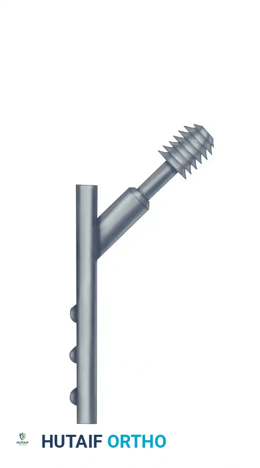
The ASIF Cancellous Screw Technique
The ASIF cancellous screw is specifically engineered for optimal purchase in the trabecular network of metaphyseal and epiphyseal bone. Unlike cortical screws, which possess a smaller pitch and shallower threads designed for dense diaphyseal bone, cancellous screws feature a larger thread diameter, deeper threads, and a wider pitch to maximize the volume of bone engaged between the threads.
Biomechanics and Indications
The ASIF cancellous screw technique is frequently utilized for screw fixation through a plate or as an independent interfragmentary lag screw. When a 4.5-mm ASIF cortical screw is used for a positional function (maintaining a fragment in place without compression), a 3.2-mm drill is selected to drill through both cortices. The screw length is determined with a depth gauge, the threads are cut along the drill hole with a 4.5-mm tap, and a fully threaded 4.5-mm cortical screw of the proper length is inserted.
Cancellous screw insertion follows a similar fundamental pathway but with critical biomechanical distinctions. Because the screw is designed to compress a metaphyseal fragment, the near cortex is not overdrilled. Instead, the unthreaded portion of the screw shaft (the shank) glides through the near cortex, ensuring that the threads only engage the far fragment.
🔪 Surgical Pearl: Bone Density Considerations
When the cancellous bone is osteoporotic or exceptionally soft, insert a washer under the head of the screw. This increases the surface area of contact, distributing the compressive load and preventing the screw head from pulling through the fragile near cortex as torque is applied.
Drill and Tap Specifications
Precision in drill and tap selection is non-negotiable to prevent thermal necrosis and ensure maximum pull-out strength:
* 4.0-mm Cancellous Screw: Use a 2.5-mm drill and a 3.5-mm tap.
* 6.5-mm Cancellous Screw: Use a 3.2-mm drill and a 6.5-mm tap.
If the metaphyseal bone is firm and hard, tapping is required, but only in the near cortex to prevent stripping the softer cancellous bone in the far fragment. Conversely, if the bone is severely osteoporotic and soft, tapping may be entirely bypassed, allowing the screw to act in a self-tapping manner, which compacts the trabeculae and marginally increases pull-out resistance.
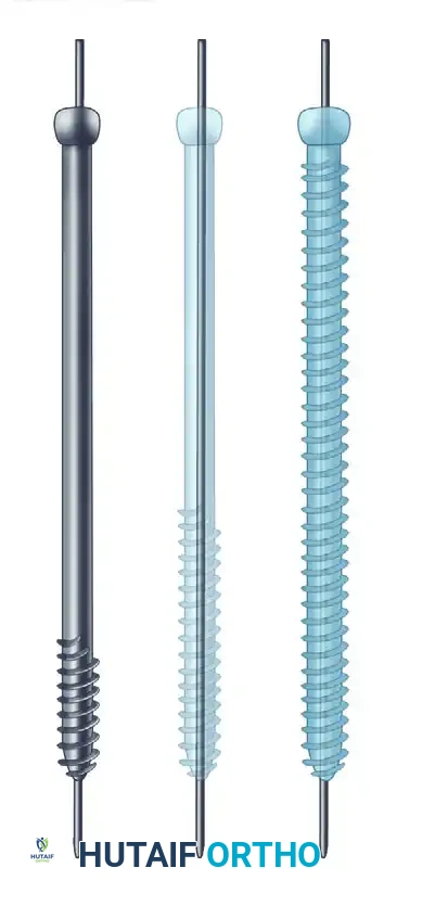
Interfragmentary Lag Screw Principles
The lag screw principle is the most effective method for achieving interfragmentary compression. It is exceptionally well-suited for the repair of avulsion fractures and intra-articular fractures where shear forces disrupt the epiphyseal and metaphyseal architecture.
To accomplish true interfragmentary compression, proper selection of the threaded portion's length is critical. The surgeon must select a thread length that places all threads entirely within the far fragment. If even a single thread engages the near fragment, the screw will act as a positional device, holding the fragments apart rather than compressing them.
Lag screw insertion. To apply compression, the thread must be engaged only in the far fragment to pull the far fragment toward the near fragment, creating absolute stability across the fracture site.
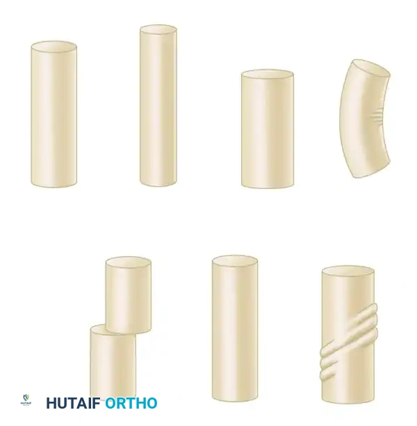
Cannulated Screw Systems
Cannulated screws represent a significant advancement in provisional and definitive fixation, particularly for small fracture fragments, femoral neck fractures, and periarticular injuries.
Various cannulated screws available for precise, guidewire-directed fixation.
The primary advantage of a cannulated system is that the ideal provisional fixation (the guidewire) serves as the exact trajectory for the definitive screw. The major technical divergence from conventional lag screw insertion is the requirement to drill over the guidewire using a cannulated drill bit. However, the fundamental principles of interfragmentary lag screw fixation—meticulous planning of screw orientation, provisional stabilization, and ensuring threads purchase only in the opposite bone fragment—remain absolute.
🔪 Surgical Technique: Small Cannulated Cancellous Bone Screws
The insertion of cannulated screws demands a systematic, step-by-step approach to avoid guidewire breakage or loss of reduction.
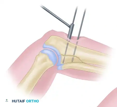
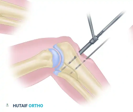
Step 1: Guidewire Insertion
After anatomical reduction is achieved and provisionally held, a 1.25-mm threaded guidewire is inserted using a small air drill and drill sleeve. The guidewire must cross the fracture orthogonally and penetrate the far cortex. Position is confirmed via fluoroscopy in multiple planes. A second, parallel anti-rotation wire is often placed.
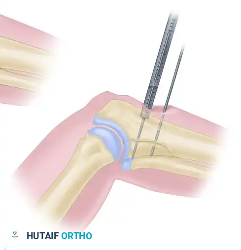
Step 2: Depth Measurement
Guidewire insertion depth is determined using a direct measuring device placed over the wire. The drilling depth is typically calculated as 5 mm less than the reading on the device to prevent inadvertent penetration of the far cortex by the drill bit.
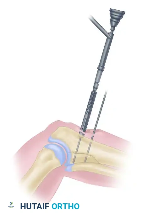
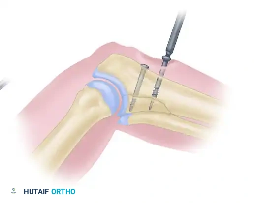
Step 3: Cannulated Drilling
The cannulated drill bit is inserted into the drill guide. The drilling assembly is placed over the guidewire, and drilling proceeds until the coupling end contacts the drill guide, ensuring the exact predetermined depth is reached without advancing the guidewire.
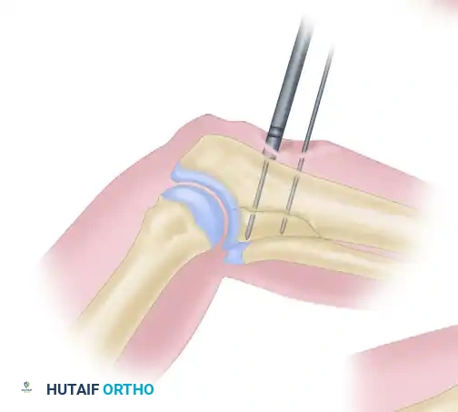
Step 4: Countersinking
A small cannulated countersink is placed over the guidewire to create a flush recess for the screw head, minimizing soft tissue irritation and ensuring even distribution of compressive forces. (A washer may be substituted in osteoporotic bone).
Step 5: Tapping
The near cortex is tapped using the cannulated tapping assembly over the guidewire.
Step 6: Screw Insertion
A small cannulated bone screw of the appropriate length is inserted over the guidewire. Once the screw is fully seated and compression is verified, the guidewire is removed.
Advanced Plate and Screw Fixation Biomechanics
Plate and screw fixation has undergone continuous evolution, transitioning from rigid, mechanically dominant constructs to biologically friendly systems that respect the periosteal blood supply.
The Tension Band Principle
Friedrich Pauwels first defined and applied the tension band principle to the fixation of fractures and nonunions. Long bones are subjected to eccentric loading, creating a tension side (convex) and a compression side (concave). The engineering principle of the tension band involves converting tensile forces into compressive forces at the fracture site.
This is achieved by placing a bone plate across the fracture on the tension (convex) side of the bone. The plate counteracts the distracting tension forces, converting them into dynamic compressive forces across the far cortex during physiological loading.
🚨 Surgical Warning: Incorrect Plate Positioning
If a plate is erroneously applied to the compression (concave) side of the bone, it provides minimal fixation. The bone will gap on the tension side, placing the plate under excessive bending stresses, inevitably leading to fatigue failure and hardware breakage.
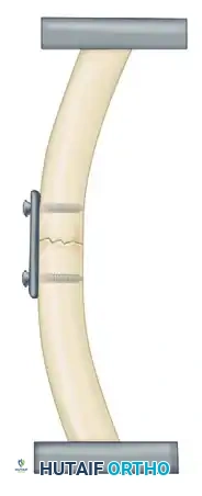
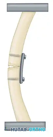
The Principle of the Tension Band Plate: A plate applied to the convex (tension) side counteracts tension forces, providing rigid internal fixation. A plate on the concave surface is subjected to overwhelming bending moments.
General Principles of Plating
Plates offer the distinct benefits of anatomical reduction and sufficient stability to allow early mobilization of musculotendinous units and adjacent joints. However, they must be protected from premature weight-bearing. Disadvantages include stress shielding (osteopenia beneath a rigid plate), plate irritation, and the risk of refracture following hardware removal.
For plates to function optimally, adequate screw fixation is mandatory. Generally, six to eight cortices of purchase are required above and below the fracture line (except when using buttress plates). A common pitfall is utilizing a plate of insufficient length; the larger the bone and the greater the physiological stresses, the longer the plate must be to increase the working length and distribute strain.
🔪 Clinical Pearl: Stress Relaxation
Overtorquing screws during initial insertion must be avoided to prevent microfractures in the cortical thread tracks. Before final wound closure, all screws should be systematically retightened. This accounts for the viscoelastic "stress relaxation" that occurs at the screw-bone interface within the first few minutes of application.
Functional Categories of Bone Plates
Plates are categorized not merely by their shape (e.g., semitubular, T-plates, L-plates, broad plates), but by their biomechanical function in a specific fracture pattern. The four primary functional categories are Neutralization, Compression, Buttress, and Bridge plates.
1. Neutralization Plates
Neutralization plates are utilized in conjunction with interfragmentary lag screws. While a lag screw provides excellent compression, it offers poor resistance to torsional, bending, and shear forces. The neutralization plate spans the fracture to "neutralize" these deforming forces, protecting the lag screw construct.
This technique is standard for type B wedge (butterfly) fractures of the humerus, radius, ulna, and fibula. The wedge fragment is first anatomically reduced and compressed with lag screws, followed by the application of the plate.

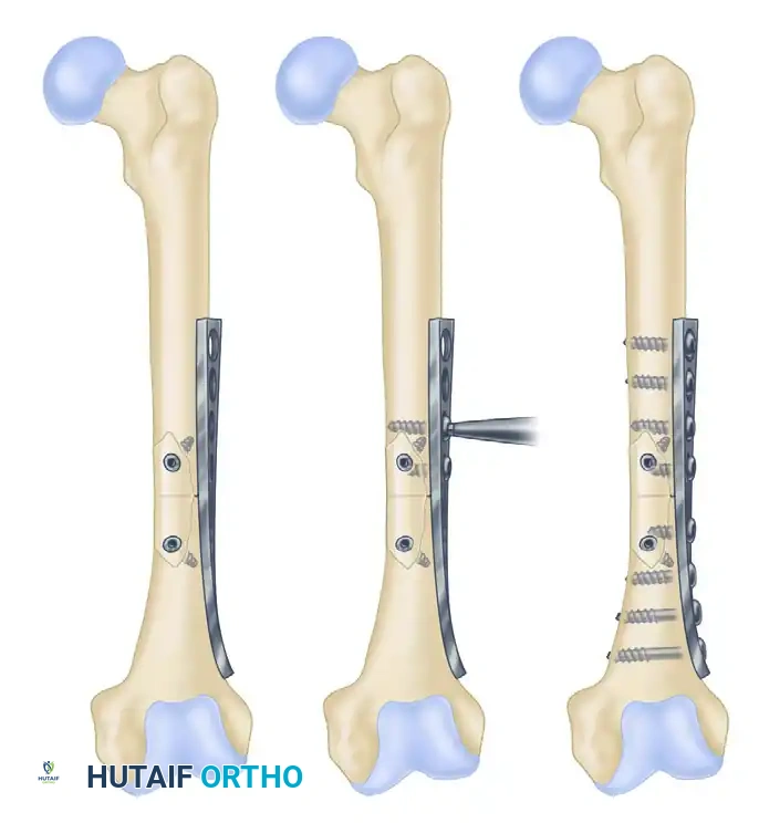
Examples of neutralization plating protecting interfragmentary lag screws.
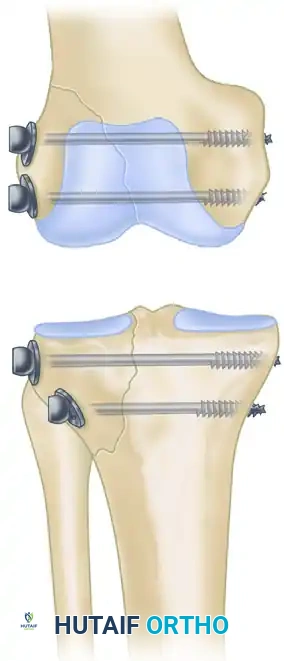
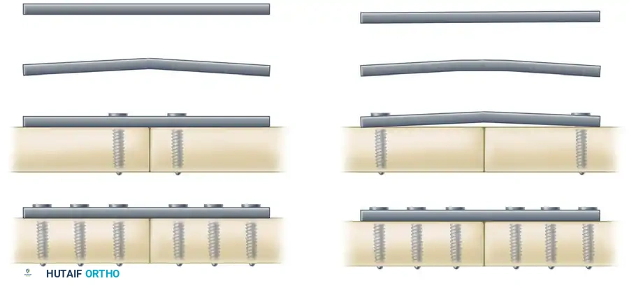
2. Compression Plates
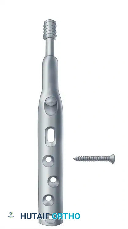
Compression plates are designed to negate torsional, bending, and shear forces while actively creating axial compression across a transverse or short oblique fracture site. This is achieved through the spherical gliding principle inherent in Dynamic Compression Plates (DCP).
As the screw head engages the specially designed undercut, eccentric hole of the DCP, it translates the plate, compressing the fracture ends together. The AO-ASIF Low-Contact Dynamic Compression Plate (LC-DCP) improved upon this by undercutting the plate's undersurface. This minimizes periosteal contact, preserving cortical perfusion, and allows for a uniform distribution of stiffness. The undercut holes also permit screw angulation of up to 40 degrees.
Dynamic compression plating utilizing eccentric screw placement to achieve axial compression.
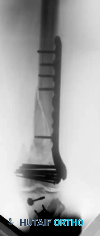
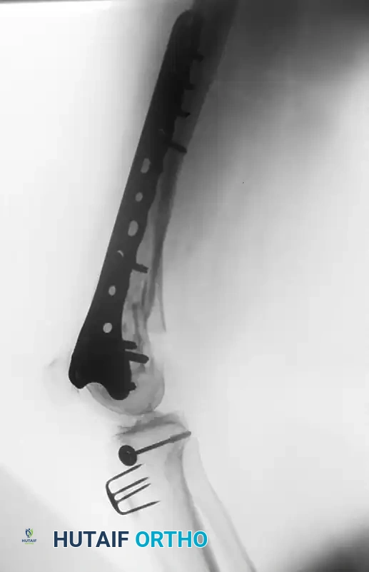
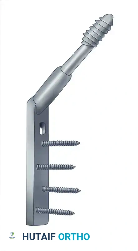
3. Buttress Plates
Buttress (or anti-glide) plates are employed to negate compressive and shear forces that drive metaphyseal-epiphyseal fragments out of alignment, commonly seen in tibial plateau and pilon fractures.
Unlike other plates, a buttress plate is anchored securely to the main stable diaphyseal fragment but is not necessarily screwed into the fragment it is supporting. Instead, it acts as a rigid retaining wall. Exact anatomical contouring is mandatory. Screws must be inserted so they adhere to the shoulder of the screw hole closest to the fracture line, preventing axial deformation under physiological loading.
4. Bridge Plates
Bridge plating is a biological fixation technique used to span highly comminuted, unstable diaphyseal fractures where anatomical reduction of every fragment would require excessive soft tissue stripping. The plate bypasses the zone of comminution, fixing only the proximal and distal main fragments. This provides relative stability, promoting secondary bone healing via robust callus formation while preserving the fracture hematoma.
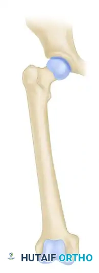
Specialized Fixation: Hip Screws and the Proximal Femur
The proximal femur presents unique biomechanical challenges due to massive bending moments and shear forces. Hip screws are specifically engineered to manage these forces in femoral neck and intertrochanteric fractures.
Early designs, such as the Jewett nail, were static devices. Modern compression hip screws (Sliding Hip Screws - SHS) allow the lag screw to slide within a barrel attached to a side plate. This controlled sliding accommodates the inevitable bone resorption and collapse that occurs during fracture healing, maintaining dynamic compression across the fracture site.
Examples of fixed and sliding hip screws. Sliding devices allow the fracture site to collapse in a controlled manner, promoting union.
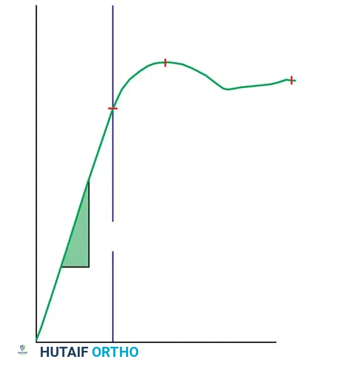
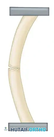
These devices operate on the tension band principle: the screw and side plate are loaded in tension, while the medial calcar of the bone is loaded in compression. The fatigue strength of the implant is heavily dependent on the angle between the side plate and the barrel.
Biomechanical studies dictate that higher-angle plates (e.g., 145 degrees) create a shorter moment arm, resulting in a significantly smaller bending moment on the implant compared to lower-angle plates (e.g., 130 degrees).
Influence of nail-plate angle on bending moment (M = F x d). A larger angle results in a smaller bending moment due to a shorter distance (d).
Postoperative Protocols and Complication Management
Successful ASIF screw and plate fixation extends beyond the operating room. Postoperative management must balance the need for early joint mobilization with the protection of the mechanical construct.
- Weight-Bearing Status: Constructs relying on absolute stability (compression plates, lag screws) in diaphyseal bone generally require protected weight-bearing until radiographic evidence of cortical bridging is observed. Bridge plates may tolerate earlier, progressive loading to stimulate secondary callus formation.
- Radiographic Surveillance: Serial radiographs are required at 2, 6, and 12 weeks to monitor for hardware failure, loss of reduction, or delayed union.
- Hardware Removal: Routine removal of asymptomatic plates is no longer recommended due to the risk of refracture through empty screw holes and the morbidity of a second operation. Removal is indicated only in cases of deep infection, prominent hardware causing soft tissue irritation (e.g., lateral malleolus, olecranon), or in pediatric patients to prevent growth tethering.
Mastery of the ASIF cancellous screw technique and the nuanced application of functional plating principles remains the cornerstone of operative fracture care, ensuring predictable, high-quality outcomes in complex orthopedic trauma.
You Might Also Like