Intramedullary and Dorsal Plate Fixation of Distal Radius Fractures
Intramedullary and Dorsal Plate Fixation of Distal Radius Fractures
DEFINITION
■Distal radius fractures typically originate in the radial meta physis and occasionally enter the radiocarpal joint and distal radioulnar joint.
■These fractures may be stable or unstable, intraarticular or extraarticular, and can be associated with various other bony and soft tissue injuries about the wrist.
■Distal radius fractures are most commonly dorsally dis placed or angulated (apex volar).
■Treatment is based on fracture stability, comminution, artic ular segment displacement, articular surface displacement, and the functional demand of the patient.
■Stability is related to initial dorsal angulation, residual dorsal angulation after closed reduction, dorsal comminu tion, age of the patient, and associated distal ulna fracture and intraarticular fracture extension.7,8
ANATOMY
■The distal radius has articulations at the scaphoid fossa, lu nate fossa, and sigmoid notch.
■The normal bony anatomy includes volar tilt of 10 degrees, radial height of 11 mm, and radial inclination of 22 degrees.
■Ulnar variance (the length of the radius relative to the ulnar head at the sigmoid notch) is variable and patient dependent.
■Dorsal ligamentous structures include the dorsal intercarpal ligament and the dorsal radiocarpal ligament.
■The dorsal radiocarpal ligament originates from the dorsal lip of the radius and attaches on the ulnar carpus.
■The dorsal intercarpal ligament represents a capsular thickening on the dorsum of the carpus, with fiber alignment perpendicular to the long axis of the radius.
■ Volar ligamentous origins include the radioscaphocapitate ligament, the long radiolunate ligament, and the short radiolu nate ligament, among others.
■The triangular fibrocartilage complex (TFCC) consists of the triangular fibrocartilage and volar radioulnar and dorsal radioulnar ligaments.
■The volar radioulnar and dorsal radioulnar ligaments orig
■The fourth compartment, containing the extensor indicis proprius and extensor digitorum communis, lies over the dorsalulnar distal radius.
■ The fifth compartment, containing the extensor digiti minimi, lies over the distal radioulnar joint.
■The sixth compartment, containing the extensor carpi ul naris, lies over the distal ulna.
PATHOGENESIS
■Distal radius fractures typically occur due to a fall on an outstretched hand.
■Fractures occur when the force of axial loading exceeds the failure strength of cortical and trabecular bone.9
■The fracture pattern is determined by the magnitude and direction of the force applied and the position of the hand during impact.3
■Dorsally displaced or angulated fractures occur when the wrist is neutral or extended and an axial or dorsally directed force is applied to the carpus.
■Osteoporosis, metabolic bone diseases, and bony tumors are risk factors for fracture.
NATURAL HISTORY
■Distal radius fractures are either stable or unstable.
■Stable fractures, treated nonoperatively, historically have excellent outcomes in terms of range of motion, pain, strength, and function.1
■Nonoperative management consists of immobilization with either a cast or a splint, molded to prevent dorsal displacement.
■Displaced, unstable, and comminuted fractures often require operative treatment.
■The goals of surgical treatment are to provide stability and improve bony alignment in order to achieve pain control, im prove range of motion, and increase function.1,6
Extensor
inate form the volar and dorsal edges of the sigmoid notch
respectively, and become confluent and insert at the base of the ulnar styloid.
■The extensor retinaculum lies superficial to the extensor ten dons and deep to the subcutaneous tissues. It has septations creating six dorsal compartments (FIG 1).
■The first compartment lies over the radial styloid and con
tains the abductor pollicis longus and the extensor pollicis brevis tendons (each may have multiple slips).
■The second compartment, containing the extensor carpi radialis longus and extensor carpi radialis brevis, lies radial to the tubercle of Lister.
■The third compartment, containing the extensor pollicis longus, lies ulnar to the tubercle of Lister.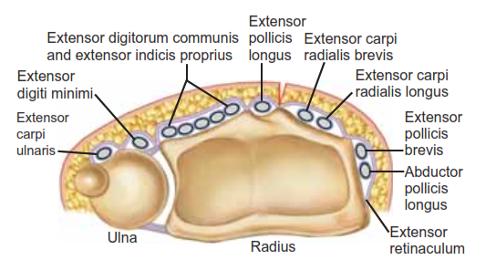
FIG 1 • Anatomy of the distal radius. The six dorsal extensor compartments at the level of the extensor retinaculum.
• One to 2 mm or more of displacement of the articular sur- face of the distal radius leads to degenerative changes in young adults.6
• Dorsal angulation of more than 20 degrees from normal (10 degrees dorsal tilt) can lead to pain, decreased range of motion, and decreased grip strength.10
• Radial shortening can decrease range of motion and cause pain with ulnar impaction of the carpus.10
PATIENT HISTORY AND PHYSICAL FINDINGS
• A history of trauma is the most common patient presentation.
• Pathologic fractures may occur with minimal stress or trauma.
• Patients complain of localized pain and present with swelling, decreased range of motion, and ecchymosis about the fracture.
• A history of previous fractures in an older patient should alert the physician to the possibility of underlying osteoporosis.
• The skin should be carefully examined to rule out the pres- ence of an open fracture and to assess swelling before surgery or casting. If the wrist is markedly swollen or if swelling is antici- pated, casting should be delayed and a splint should be placed.
• Neurologic symptoms in the form of numbness, tingling, and radiating pain into the digits should alert the physician to the possibility of acute carpal tunnel syndrome. Careful neuro- logic assessments should be performed to rule out the presence of a progressive neurologic deficit.
• Acute carpal tunnel syndrome represents a surgical emergency.
• Examination:
• Remove splints and dressings to visualize all areas of skin.
• Palpate for areas of tenderness or deformity. Palpate anatomic snuffbox.
• Visualize and palpate the elbow for swelling, ecchymosis, tenderness, crepitus, and deformity.
• Visualize and palpate the hand and fingers for swelling, ecchymosis, tenderness, crepitus, and deformity.
• Use two-point tool or paper clip bent to 5 mm and touch radial and ulnar aspects of all fingers with one or two points. Greater than normal (5 mm) two-point testing in the form of progressive neurologic deficit may signify an acute or chronic carpal tunnel syndrome.
IMAGING AND OTHER DIAGNOSTIC STUDIES
• Posteroanterior (PA), lateral, and oblique radiographic views are critical in evaluating all suspected distal radius fractures.
• Consider imaging the uninjured wrist for comparison and to serve as a template for surgical reconstruction.
• Radiographs of the elbow should be obtained in almost all cases, especially if any tenderness, swelling, or deformity is detected clinically.
• Radiographic measurements taken from the PA view
(FIG 2A) include9,13:
• Radial inclination, which is the angle between a line per- pendicular to the shaft of the radius at the articular margin and a line along the radial articular margin
• Normal angle = 21 degrees
• Radial length, which is the distance from a line tan- gential to the ulnar articular margin to a line drawn per- pendicular to the long axis of the radius at the radial styloid tip
• Normal length = 11 mm
• Ulnar variance, which is the distance from a line perpen- dicular to the long axis of the radius at the sigmoid notch and a line tangential to the ulnar articular surface
• Ulnar variance is variable, so to establish a normal value, radiographs of the normal contralateral side should be obtained.
• Lateral articular (volar) tilt is the angle between a line for the articular surface of the radius and a perpendicular line to the long axis of the radius.
• Normal angle = 11 degrees volar tilt (FIG 28)9,13
• CT scans can fully elucidate the anatomy of the fracture, particularly articular disruption or incongruity, and also help to determine the necessary surgical approach based on the lo- cation and extent of comminution.
• CT scans increase the interobserver reliability of treat- ment plans and may actually alter the initial treatment plan based on plain radiographs.5
• MRI can be useful in evaluating for concomitant ligamen- tous injuries, TFCC injuries, stress fractures, and occult carpal fractures.
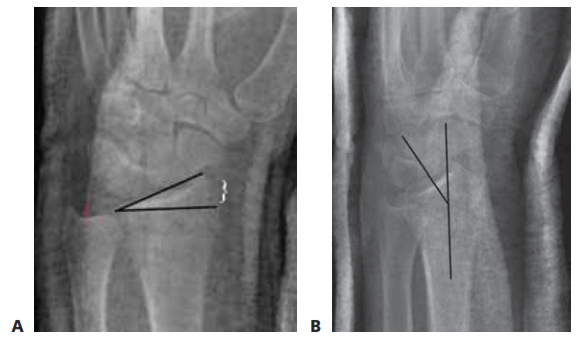
FIG 2 • A. PA radiograph demonstrating radial inclination, (black lines), ulnar variance (red), and radial height (white bracket). 8. Lateral radi- ograph of the wrist demonstrating volar tilt (black lines).
DIFFERENTIAL DIAGNOSIS
• Bony contusion
• Wrist dislocation
• Scaphoid or other carpal fracture
• Carpal instability or dislocation
• Distal ulna fracture
• Wrist ligament or TFCC sprain or tear
NONOPERATIVE MANAGEMENT
• Closed reduction should be performed in the emergency department with longitudinal axial traction followed by volar displacement of the carpus. A bivalved, short-arm, well- molded cast or sugar-tong splint should be applied.
• Casting is the most commonly used method to definitively treat distal radius fractures and is preferred for nondisplaced or minimally displaced fractures and those that are stable after a reduction maneuver (ie, restored volar tilt with minimal dor- sal comminution). A precise three-point mold is required to maintain fracture reduction.
• Removable splinting can be considered when treating com- pletely nondisplaced stable fractures in young adults.
• If nonoperative treatment is chosen, repeat radiographs should be taken on a weekly basis for the first 3 weeks to ensure that the reduction is maintained. The physician should have a low threshold for changing the cast.
• Any sign of dorsal migration indicates instability, and oper- ative stabilization should be considered.
• Finger range of motion is begun immediately and wrist range of motion can be started as the fracture heals and is managed in a removable splint.
SURGICAL MANAGEMENT
• Open reduction and internal fixation with a dorsal plate can be used successfully in the treatment of displaced, unstable, comminuted fractures of the distal radius that fail to respond to closed treatment.
• Dorsal plating buttresses the fracture to correct deformity and maintain fracture reduction.
• New intramedullary implants have been designed to alle- viate some of the complications associated with traditional
dorsal plates and allow a less invasive option for fixation of dorsally displaced fractures (FIG 3A,B).
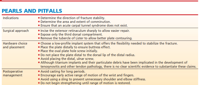
• Indications for dorsal plating include:
• Severe initial dorsal displacement (>20 degrees from nor- mal, 10 degrees dorsal tilt)
• Marked dorsal comminution (greater than or equal to
50% of the diameter of the radius shaft on the lateral radiograph)
• Residual (after reduction) dorsal tilt greater than 10 de- grees past neutral
• 10 mm of radius shortening
• Dorsal intra-articular fragments displaced more than
1 mm1,6
• Stabilization using an intramedullary device is indicated for distal radius fractures without extensive articular involvement in which a limited incision and shorter procedure are desired (see Tech Fig 4E).
• Comminution of the volar metaphysis is a relative con- traindication for the use of a dorsal intramedullary implant.
• The surgeon should be prepared to change management in- traoperatively and must have additional stabilization options available, if necessary, such as percutaneous pins or an exter- nal fixator.
Preoperative Planning
• All radiographic imaging must be reviewed before surgery.
• It is helpful to compare radiographs of the injured wrist to the uninjured wrist.
• Displaced intra-articular fragments must be identified.
• Dorsal comminution must be evaluated to determine frac- ture stability and the need for bone grafting.
• The distal extent of the fracture must be determined to enable the buttress plate to function properly.
• Bone should be evaluated for osteopenia, osteoporosis, and tumors.
Positioning
• The patient is placed supine on a regular operating table.
• A tourniquet is placed near the axilla with the splint in place.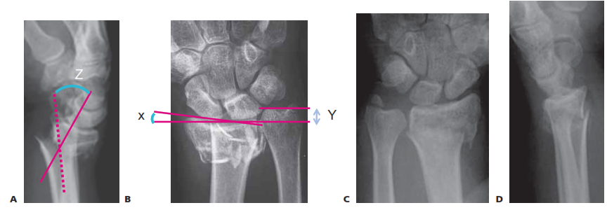
FIG 3 • PA radiograph (A) and lateral radiograph (B) of a healed distal radius fracture fixed with an intramedullary plate. C,D. PA and lateral radiographs showing an unstable metaphyseal distal radius fracture. (C,D: copyright Thomas R. Hunt III, MD.)
■ After anesthesia has been administered, the arm is placed on a radiolucent hand table (FIG 4).
■ Motion of the shoulder and elbow should be adequate to
allow adequate reduction and positioning.
■ Image intensification using fluoroscopy should be per- formed throughout the procedure to assess fracture reduction and the position of the hardware.
Approach
■ The dorsal approach to the distal radius through the third dorsal compartment with subperiosteal elevation of the com- partments provides the exposure needed to place a dorsal plate while protecting the extensor tendons from the plate and screws.
■ This approach helps to minimize adhesions and the risk of tenosynovitis and tendon rupture.
■ The approach used to place an intramedullary device de- pends on the nature of the implant and the location and extent of the fracture.
■ Dorsal intramedullary implants are placed through a limited dorsal approach through the third extensor compartment.
■ Radial intramedullary implants are placed through a small radial incision with careful protection of the radial sensory nerve
.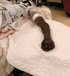
FIG 4 • Patient is positioned supine with arm on a hand table and tourniquet applied on proximal arm.
DORSAL PLATE FIXATION OF DISTAL RADIUS FRACTURES
Incision and Dissection
■ The skin incision is centered over the tubercle of Lister
(TECH FIG 1A).
■ The subcutaneous tissues are dissected down to extensor retinaculum, with care to preserve any sensory nerve branches while obtaining hemostasis with bipolar elec- trocautery (TECH FIG 1B).
■ The extensor retinaculum is incised just ulnar to the tu-
bercle of Lister, exposing the extensor pollicis longus
(EPL) tendon (TECH FIG 1C).
■ The hematoma is evacuated and the EPL tendon is freed proximally and distally by incising the septa of the third compartment (TECH FIG 1D).
■ The EPL tendon can then be removed from the third compartment and protected for the rest of the surgical procedure.
■ The extensor compartments are subperiosteally elevated
using a scalpel in radial and ulnar directions to expose the dorsal cortex of the distal radius (TECH FIG 1E,F).
■ If properly maintained, the periosteum of the exten-
sor compartments can be repaired after placement of the fixation device and will serve as a barrier between the dorsal plate and the extensor tendons.
■ The tubercle of Lister is almost invariably involved in the
fracture and should be completely removed using a rongeur (TECH FIG 1G).
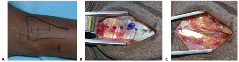
TECH FIG 1 • A. Skin incision is drawn in relation to the tubercle of Lister. B. Skin incision is carried down to extensor reti- naculum. Tubercle of Lister and retinacular incision are drawn. C. The retinaculum is incised and the EPL tendon is exposed. Hematoma has already been evacuated. (continued)
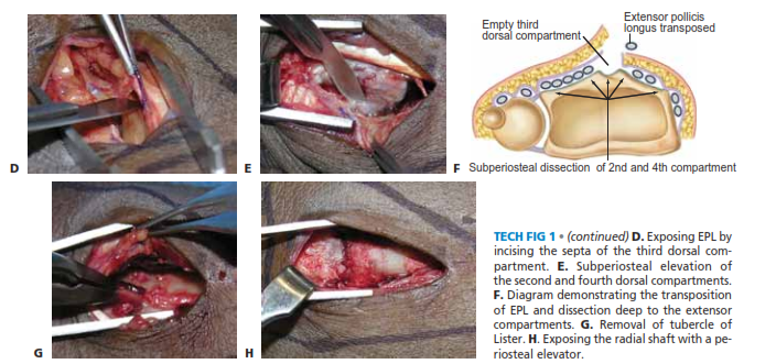
TECH FIG 1 • (continued) D. Exposing EPL by incising the septa of the third dorsal com- partment. E. Subperiosteal elevation of the second and fourth dorsal compartments. F. Diagram demonstrating the transposition of EPL and dissection deep to the extensor compartments. G. Removal of tubercle of Lister. H. Exposing the radial shaft with a pe- riosteal elevator.
■ The radius shaft is exposed with a periosteal elevator
(TECH FIG 1H).
Reduction and Plate Fixation
■ Reduction is obtained and confirmed using axial traction and palmar translation of the hand (TECH FIG 2A).
■ If reduction of articular fragments is needed, the radial
portion of the origin of the dorsal radiocarpal ligament can be elevated sharply off the radius to evaluate the ar- ticular surfaces.
■ Kirschner wires can be used for temporary fixation.
■ Bone graft is inserted to support reduced articular fragments.
■ The dorsal plate is applied directly on the radius (TECH
FIG 2B).
■ The plate is secured beginning with a bicortical screw in the oval sliding hole.
■ Fracture reduction and placement of the plate are con-
firmed using fluoroscopy.
■ The plate is secured to the distal fragment with one or two cancellous screws. The surgeon should avoid placingthe distal, ulnar screw if possible as this may irritate the overlying digital extensor tendons in the fourth dorsal compartment.the distal, ulnar screw if possible as this may irritate the overlying digital extensor tendons in the fourth dorsal compartment.
■ Additional cortical screws are added in the radius shaft.
■ Reduction and stability are confirmed (TECH FIG 2C,D).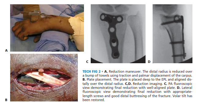
TECH FIG 2 • A. Reduction maneuver. The distal radius is reduced over a bump of towels using traction and palmar displacement of the carpus. B. Plate placement. The plate is placed deep to the EPL and aligned dis- tally over the distal radius. C,D. Reduction imaging. C. PA fluoroscopic view demonstrating final reduction with well-aligned plate. D. Lateral fluoroscopic view demonstrating final reduction with appropriate- length screws and good distal buttressing of the fracture. Volar tilt hasbeen restored.
Wound Closure
■ The wound is copiously irrigated.
■ The retinaculum is closed deep to the transposed EPL
tendon, incorporating the periosteal layer that forms the
floor of the extensor compartments (TECH FIG 3A). A
■ The skin is closed with nylon suture (TECH FIG 3B).
■ A volar splint is applied.
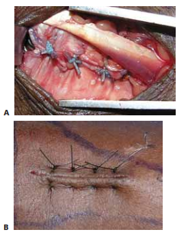
TECH FIG 3 • A. Retinacular closure. The extensor retinaculum is closed deep to the EPL with a nonabsorbable suture. B. Skin closure. The skin is closed with a horizontal mattress stitch toevert the skin edges.
FIXATION OF DISTAL RADIUS FRACTURES USING A DORSAL INTRAMEDULLARY DEVICE (TORNIER)
■ The fracture is exposed using a limited version of the incision detailed for placement of a dorsal plate (TECH FIG 4A).
■ The extensor retinaculum is incised just ulnar to the
tubercle of Lister, exposing the EPL tendon.
■ The EPL tendon is freed proximally and distally by in- cising the septa of the third compartment.
■ The EPL tendon can then be transposed for the rest of
the surgical procedure.
■ A scalpel is used to subperiosteally elevate the fourth and portions of the second extensor compartment in ra- dial and ulnar directions.
■ The dorsal cortex of the distal radius is exposed and
room is created for seating of the extramedullary por- tion of the device.
■ The tubercle of Lister is removed and an awl is used to create an entry point in the dorsal cortex (TECH FIG 4B).
■ This usually involves a portion of the fracture line.
■ The canal is rasped until the rasp may be fully seated
(TECH FIG 4C).
■ The implant is placed using the insertion device to con- trol rotation (TECH FIG 4D).
■ Fracture reduction is typically achieved as the device
is inserted and seated due to its buttress effect and three-point fixation in the canal.
■ Lag screws are inserted as required, followed by a cover
lock to create fixed angle stability.
■ Reduction and stabilization are confirmed radiographi- cally (TECH FIG 4E,F).
■ Wound closure and splinting are as described above.
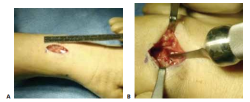
TECH FIG 4 • A. A 2.5-cm dorsal incision is used for exposure. B. The awl is inserted through the fracture site after removal of the tubercle of Lister. (continued)
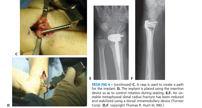
TECH FIG 4 • (continued) C. A rasp is used to create a path for the implant. D. The implant is placed using the insertion device so as to control rotation during seating. E,F. An un- stable metaphyseal distal radius fracture has been reduced and stabilized using a dorsal intramedullary device (TornierCorp). (E,F: copyright Thomas R. Hunt III, MD.)
FIXATION OF DISTAL RADIUS FRACTURES USING A RADIAL INTRAMEDULLARY DEVICE (WRIGHT MEDICAL)
■ A 2- to 3-cm incision is made over the radial styloid, be- tween the first and second extensor compartments.
■ Care is taken to protect branches of the radial sensory
nerve.
■ A cannulated drill is used to penetrate the cortex 2 to
3 mm proximal to the radiocarpal joint line to create the entry point.
■ After insertion of a starter awl, the canal is broached se-
quentially under fluoroscopic guidance to fit the medullary canal.
■ The implant is then inserted with the insertion jig, mak-
ing sure the implant is countersunk into the radial styloid.
■ The proximal interlocking screws are then placed using the insertion jig, using small incisions of the dorsal aspect of the forearm.
■ The distal interlocking screws are placed last using the in-
sertion jig.
■ Small adjustments to radial height and tilt can be made at this time.
■ Reduction and stabilization are confirmed radiographi-
cally.
■ Wound closure and splinting are as described above.
PEARLS AND PITFALLS
POSTOPERATIVE CARE
■ Postoperatively the patient is placed in a bulky dressing that allows motion of the digits, elbow, and shoulder. A volar rest- ing splint may be used to support the wrist if there is any con- cern about fixation strength.
■ The patient is encouraged to begin finger range-of-motion exercises immediately after surgery.
■ Seven to 10 days after surgery the sutures are removed, Steri-Strips are applied, and the incision is allowed to get wet.
■ The patient is evaluated by an occupational therapist, who provides a thermoplastic splint, and can start active and ac- tive-assisted range-of-motion exercises depending on fracture stability.
■ When the fracture heals at about 6 weeks, gentle passive range of motion and strengthening may be started.
OUTCOMES
■ Dorsal plating has recently been shown biomechanically to be stronger and stiffer than volar plating for dorsally unstable fractures.12
■ Dorsal plating has been associated with a higher complica- tion rate than other means of stabilization.2,9,10
■ Extensor tenosynovitis and tendon rupture have been prevalent in the past, mainly due to bulky implants.
■ There has been renewed interest in dorsal plating of the dis- tal radius as it has been shown to have a low rate of tendon- related complications with the use of low-profile, anatomic implants.4,10,11
■ Clinical reports have suggested that low-profile systems are more important in satisfactory outcomes for dorsal plating, with a much lower rate of complications.10
■ Fixation with low-profile dorsal plates can result in at least
80% of contralateral wrist range of motion, about 80% to
90% of grip strength, and over 90% pinch strength, with min- imal risk of tendon rupture.4,11
COMPLICATIONS
■ Infection (pin tract or deep)
■ Injury to tendons, vessels, and nerves
■ Stiffness
■ Posttraumatic arthritis
■ Weakness in grip or pinch
■ Tenosynovitis and tendon ruptures
■ Malunion or nonunion
■ Compartment syndrome
■ Carpal tunnel syndrome
■ Late tendon rupture, potentially related to implant design and material
■ Hardware failure
■ Complex regional pain syndrome type I
DISCLOSURE
Dr. Beredjiklian is a stockholder with and consultant for
Tornier, Inc.
REFERENCES
1. Glowacki KA, Weiss AP, Akelman E. Distal radius fractures: con- cepts and complications. Orthopedics 1996;19:601–608.
2. Grewal R, Perey B, Wilmink M, Stothers K. A randomized prospec- tive study on the treatment of intra-articular distal radius fractures: open reduction and internal fixation with dorsal plating versus mini open reduction, percutaneous fixation, and external fixation. J Hand Surg Am 2005;30A:764–772.
3. Jupiter JB, Fernandez DL. Comparative classification for fractures of the distal end of the radius. J. Hand Surg Am 1997;22A:563–571.
4. Kamath AF, Zurakowski D, Day CS. Low-profile dorsal plating for dorsally angulated distal radius fractures: an outcomes study. J Hand Surg Am 2006;31A:1061–1067.
5. Katz MA, Beredjiklian PK, Bozentka DJ, et al. Computed tomogra- phy scanning of intra-articular distal radius fractures: does it influ- ence treatment? J Hand Surg Am 2001;26A:412–421.
6. Knirk JL, Jupiter JB. Intra-articular fractures of the distal end of the radius in young adults. J Bone Joint Surg am 1986;68A:647–659.
7. Lafontaine M, Hardy D, Delince P. Stability assessment of distal ra- dial fractures. Injury 1989;20:208–210.
8. Mackenney PJ, McQueen MM, Elton R. Prediction of instability in distal radial fractures. J Bone Joint Surg Am 2006;88A:1944–1951.
9. Nana AD, Joshi A, Lichtman DM. Plating of the distal radius. J Am
Acad Orthop Surg 2005;13:159–171.
10. Rozental TD, Beredjiklian PK, Bozentka DJ. Functional outcome and complications following two types of dorsal plating for unstable frac- tures of the distal part of the radius. J Bone Joint Surg Am 2003;85A:
1956–1960.
11. Simic PM, Robison J, Gardner MJ, et al. Treatment of distal radius fractures with a low-profile dorsal plating system: an outcomes as- sessment. Hand Surg Am 2006;31A:382–386.
12. Trease C, McIff T, Toby EB. Locking versus nonlocking T-plates for dorsal and volar fixation of dorsally comminuted distal radius frac- tures: a biomechanical study. Hand Surg Am 2005;30A:756–763.
13. Trumble TE, Culp R, Hanel DP, et al. Intra-articular fractures of the distal aspect of the radius. J Bone Joint Surg Am 1998;80A:582–600.