
Femoral Neck Fractures
Open Reduction and Internal Fixation and Closed Reduction and Percutaneous Fixation of Femoral Neck Fractures
DEFINITION
■ Femoral neck fractures occur in two patient populations.
■ Most commonly, they happen in older, osteopenic pa- tients after low-energy trauma, such as falls.
■ When they occur in younger patients with normal bone, they are usually the result of high-energy trauma, such as a motor vehicle collision.
■ Femoral neck fractures can be classified by several charac- teristics. The most important distinguishing feature in regard to treatment decisions is the degree of displacement.
■ Fractures that are nondisplaced or impacted into valgus can usually be treated with fixation in situ using percuta- neous methods.
■ Displaced fractures usually require reduction and fixation or replacement.
■ The location of the fracture in the femoral neck can be described as subcapital, transcervical, or basicervical (FIG 1).
■ Transcervical femoral neck fractures can be further charac-
terized by the angle of the fracture line with respect to the perpendicular of the femoral shaft axis. This is the Pauwels classification (Table 1).
■ The importance of this feature is to recognize high-angle fractures (more vertical), which have the greater risk of dis- placement when treated with screws along the neck axis.
ANATOMY
■ The femoral neck axis forms an angle of about 140 degrees to the femoral shaft axis. In addition, it is anteverted about 15 de- grees with reference to the plane of the posterior condyles of the distal femur.

FIG 1 • Definition of location for femoral neck fractures. Fractures through the red zone are described as basicervical, in the yellow zone they are transcervical, and in the green area they are designated subcapital.
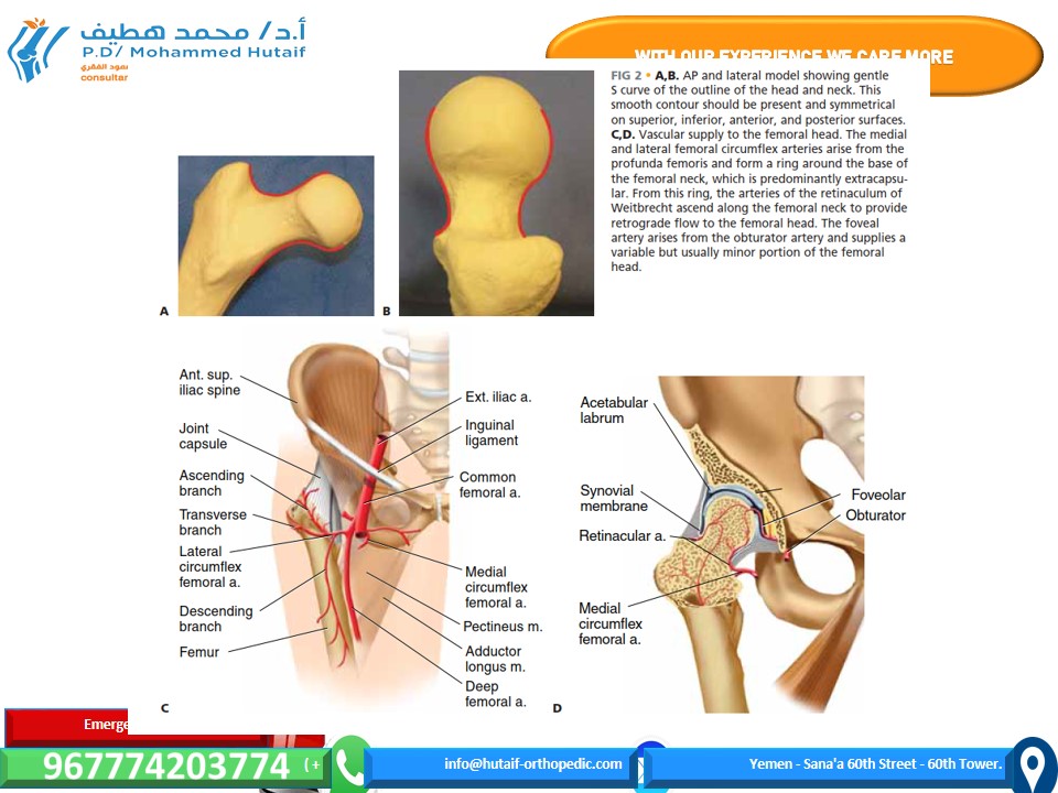
■ When viewed in both anteroposterior (AP) and lateral radi- ographic views, the normal contour of the femoral head and neck forms a gentle S (FIG 2A,B).
■ The vascular supply of the proximal femur relies on the me-
dial femoral circumflex artery, particularly the posterior branch, which feeds the retinacula of Weitbrecht. Minor contributions come from the artery of the ligamentum teres (FIG 2C,D).
PATHOGENESIS
■ Low-energy femoral neck fractures generally are a result of a fall from standing height in an osteoporotic individual.
■ This is an increasing public health problem, with projec- tions of 512,000 total hip fractures in the United States by the year 2040.1
■ High-energy (comminuted) femoral neck fractures generally result from high-speed motor vehicle collision or falls from greater than 10 feet.
■ These patients frequently have multiple injuries, which can complicate treatment.
NATURAL HISTORY
■ Nondisplaced or minimally displaced fractures that are not surgically stabilized are likely to suffer worsened displacement owing to the high mechanical forces associated with hip mo- tion and the instability that comes from comminution of the cortical bone.
■ The intra-articular location of the femoral neck means that there is not a well-vascularized soft tissue envelope, and the fracture is exposed to synovial fluid, which contains enzymes that lyse blood clot, the required first stage in bone healing. As a result, femoral neck fracture healing is slowed.
■ In addition, the blood supply comes from tenuous retro- grade blood flow.
■ Nonunion rate for untreated displaced fractures approaches
100%.
■ Nonunion of the femoral neck leads to a shortened limb, variable restriction in motion, and pain with weight bearing.
■ Fracture of the femoral neck can lead to interruption of the blood supply to the femoral head due to kinking or disruption of vessels or tamponade from hemarthrosis.
■ This results in avascular necrosis in about 15% of cases.2
■ Many surgeons believe that time to treatment is an impor- tant factor, with delay increasing the incidence. This is diffi- cult to prove, and the time imperative probably varies from patient to patient.
■ Femoral neck fractures in the elderly are associated with about 20% 1-year mortality.4
■ About 50% of patients return to their previous level of func- tion after surgery.3
PATIENT HISTORY AND PHYSICAL FINDINGS
■ In most patients with femoral neck fracture, the history will contain a distinct traumatic episode, after which the patient could not ambulate.
■ Physical findings reveal limb shortening, external rota- tion, and pain on attempted hip motion.
■ In some patients, the onset of pain is more insidious.
■ It is usually associated with weight bearing, and it is lo- cated in the groin rather than in the buttock or trochanteric area.
■ In the case of a stress fracture, the history of increased activity over a short period of time is suggestive.
■ Night or rest pain suggests pathologic fracture or impend- ing fracture.
■ In highly osteoporotic patients with minor trauma, a history of groin pain with weight bearing may be a symptom of occult femoral neck fracture, which is a nondisplaced fracture not visible on plain radiographs.
■ Physical examination should include:
■ Observation of the lower extremities with comparison of foot position in the supine patient. A shortened, externally rotated limb indicates fracture.
■ Gait observation. Groin pain on attempted weight bear- ing or an antalgic gait suggests occult femoral neck fracture.
■ Internal and external rotation. Pain in the groin is con- cerning for femoral neck fracture but may also be caused by fractures of the anterior pelvic ring.
■ Impaction of the heel of the injured leg. Groin pain that did not exist at rest implies hip fracture.
IMAGING AND OTHER DIAGNOSTIC STUDIES
■ Standard plain radiographs consist of an AP view of the pelvis and AP and frog-leg lateral films of the hip.
■ An AP traction film with internal rotation can be helpful if initial films are difficult to interpret in terms of the location of injury or fracture pattern.
■ If clinical suspicion is high (eg, an elderly patient who can- not ambulate because of groin pain) but plain radiographs are negative, a bone scan or MRI may be obtained for low-energy injuries.
■ The bone scan will not turn positive for 24 to 72 hours, but the MRI should be diagnostic within hours of injury.
■ Some studies have suggested that any multiply injured pa- tient with a high-energy femur fracture should have imaging of the femoral neck with a CT scan in addition to plain films to identify minimally displaced femoral neck fractures. However, the CT scan may be false negative as well, and the routine use of this modality is controversial.
Table 1 Pauwels Classification of Transcervical Femoral Neck Fractures
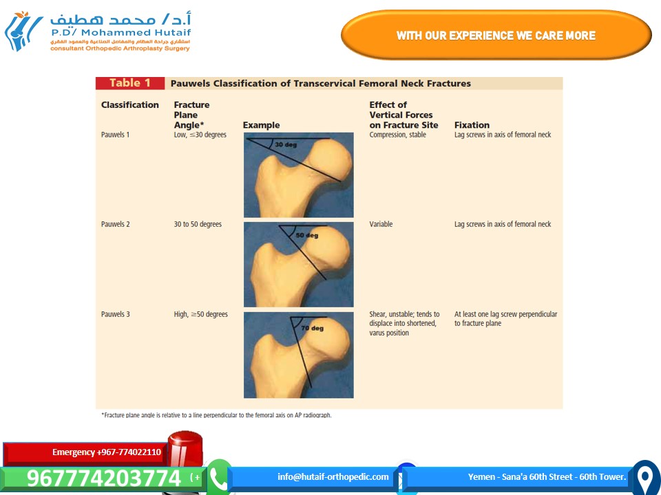
FIG 2 • A,B. AP and lateral model showing gentle S curve of the outline of the head and neck. This smooth contour should be present and symmetrical on superior, inferior, anterior, and posterior surfaces. C,D. Vascular supply to the femoral head. The medial and lateral femoral circumflex arteries arise from the
profunda femoris and form a ring around the base of the femoral neck, which is predominantly extracapsu- lar. From this ring, the arteries of the retinaculum of Weitbrecht ascend along the femoral neck to provide retrograde flow to the femoral head. The foveal artery arises from the obturator artery and supplies a variable but usually minor portion of the femoral head.
DIFFERENTIAL DIAGNOSIS
■ Intertrochanteric, pertrochanteric, or subtrochanteric fracture
■ Anterior pelvic ring (ramus) fracture
■ Hip dislocation
■ Femoral head fracture
■ Pathologic lesion, including neoplasm or infection
■ Arthritis
■ Avascular necrosis
■ Contusion
■ Muscle strain
NONOPERATIVE MANAGEMENT
■ Nonoperative treatment may be appropriate in patients who are nonambulators, neurologically impaired, moribund, or in extremis.
■ Nonoperative treatment should initially consist of bed rest, appropriate analgesia, protection against decubitus ulcers, and appropriate medical supportive treatment.
■ Buck’s traction or pillow splints may be helpful in reduc- ing pain.
■ As soon as pain control is adequate, patients should be mo- bilized out of bed to a chair to help prevent the complications of bed rest, such as pneumonia, aspiration, skin breakdown, and urinary tract infection.
■ Some valgus impacted fractures may be treated nonopera- tively, particularly if discovered after several weeks, but there is a risk of displacement of up to 46%.
■ Nonoperative treatment for these patients should consist of mobilization on crutches or a walker.5
■ Stress fractures may be treated nonoperatively if they are caught early and are nondisplaced and if the fracture line does not extend to the tension side or superior neck.
SURGICAL MANAGEMENT
■ Most patients with femoral neck fracture should be consid- ered for surgical treatment.
■ Displaced femoral neck fractures in some patient po- pulations may be better served by hemiarthroplasty or total hip arthroplasty, which is beyond the scope of this chapter.
■ This includes elderly patients, osteoporotic patients, those with neurologic disease, patients with preexisting hip arthritis, and those with medical illnesses impairing bone heal- ing or longevity (eg, renal failure, diabetes, malignancy, or an- ticonvulsant treatment).
■ Nondisplaced fractures, valgus-impacted femoral neck frac- tures in the elderly, or stress fractures in athletes can be treated with fixation in situ through percutaneous techniques.
■ Open reduction and internal fixation is the standard for high- energy injuries in younger healthy patients with good bone.
■ Closed reduction of a displaced femoral neck fracture in the young patient is difficult, and one should not accept a less- than-perfect reduction to avoid an open procedure.
■ The quality of the reduction is the most important surgeon-controlled factor in outcome.
Preoperative Planning
■ Once the decision for operative treatment is made, preoper- ative planning begins with evaluation of patient-specific fac- tors that may alter the timing or technique for fixation of the femoral neck fracture.
■ In the elderly population, optimization of medical condi- tions is advisable, including evaluation of hydration and cardiac and pulmonary function, and management of chronic medical conditions. However, delay of surgery be- yond the first 2 to 4 days increases the risk of perioperative complications and the length of stay.
■ In younger patients, it is important to consider other in- juries that may affect operative positioning or fixation. For example, ipsilateral lower extremity injuries at another level may affect the use of the fracture table.
■ Good-quality radiographs in two planes are necessary to understand the location and orientation of the fracture. In some cases, radiographs of the contralateral side may help select an implant with the correct length, diameter, or neck– shaft angle.
■ The anticipated implants should be verified present before the case. It is useful to have arthroplasty instruments and im- plants in the hospital in the event of unexpected findings. Fortunately, this will rarely be needed.
■ Nondisplaced fractures in the subcapital or transcervical re- gion can be treated with two or three cannulated screws, but most surgeons believe that basicervical fractures should be treated with a fixed-angle device, such as a sliding hip screw or cephalomedullary nail.
Positioning
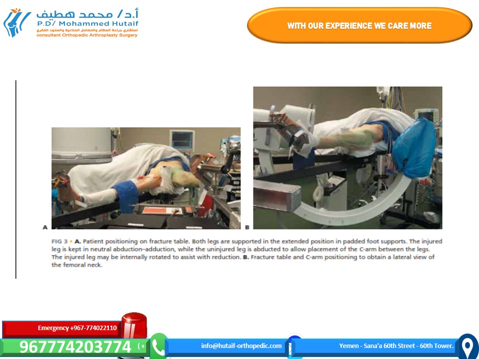
■ The patient is positioned on a fracture table with both hips extended. The contralateral leg is abducted to allow the C-arm to be positioned between the legs (FIG 3A).
■ Owing to the risk of compartment syndrome, the surgeon
should avoid using the “well leg holder,” which puts the contralateral leg in a hemi-lithotomy position (hip and knee flexed, elevating the leg).
■ Intraoperative fluoroscopy is used, and good visualization of the hip and the fracture reduction in both AP and lateral projec- tions should be verified before preparing the leg (FIG 3B).
■ A closed reduction may sometimes be obtained by applying
gentle traction and internal rotation under fluoroscopic con- trol (Fig 3A). Vigorous and complicated reduction maneuvers are unlikely to be effective and should be avoided. If simple, gentle positioning is not successful in achieving acceptable position, open reduction should be strongly considered. The patient should be well relaxed by the anesthesia team.
■ Reduction is anatomic when the normal contours of the femoral neck are re-established in both the AP and lateral pro- jections (see Fig 2A,B), the normal neck–shaft angle and neck length are restored (as judged from a film of the contralateral hip, or AP pelvis), the relative heights of the femoral head and trochanter are symmetrical to the contralateral side, and no gaps are seen in the fracture.
■ If the C-arm images are of poor quality because of patient obesity or other factors, the surgeon must not assume or hope it will be better intraoperatively. If adequate visualization to
FIG 3 • A. Patient positioning on fracture table. Both legs are supported in the extended position in padded foot supports. The injured leg is kept in neutral abduction–adduction, while the uninjured leg is abducted to allow placement of the C-arm between the legs.
The injured leg may be internally rotated to assist with reduction. B. Fracture table and C-arm positioning to obtain a lateral view of the femoral neck.assess reduction or implant position is not achievable, open reduction under direct visualization is the prudent course.
Approach
■ A standard lateral approach is used for percutaneous fixa- tion of nondisplaced or valgus impacted fractures.
■ If an open reduction is planned, a Smith-Peterson or Watson-Jones approach may be used according to surgeon preference to afford visualization of the anterior femoral neck.
■ The Watson-Jones approach is the senior author’s prefer- ence and is described below.
CLOSED REDUCTION AND PERCUTANEOUS FIXATION
■ The patient is positioned on the fracture table and re- duction is obtained as noted above, C-arm visualization is verified, and the leg and hip is prepared and draped in a sterile fashion.
■ Preoperative antibiotics are given.
Guidewire and Screw Placement
■ Guidewires for cannulated screws are placed in line with the femoral neck axis through poke holes.
■ The wires are placed parallel, using a parallel drill
guide.
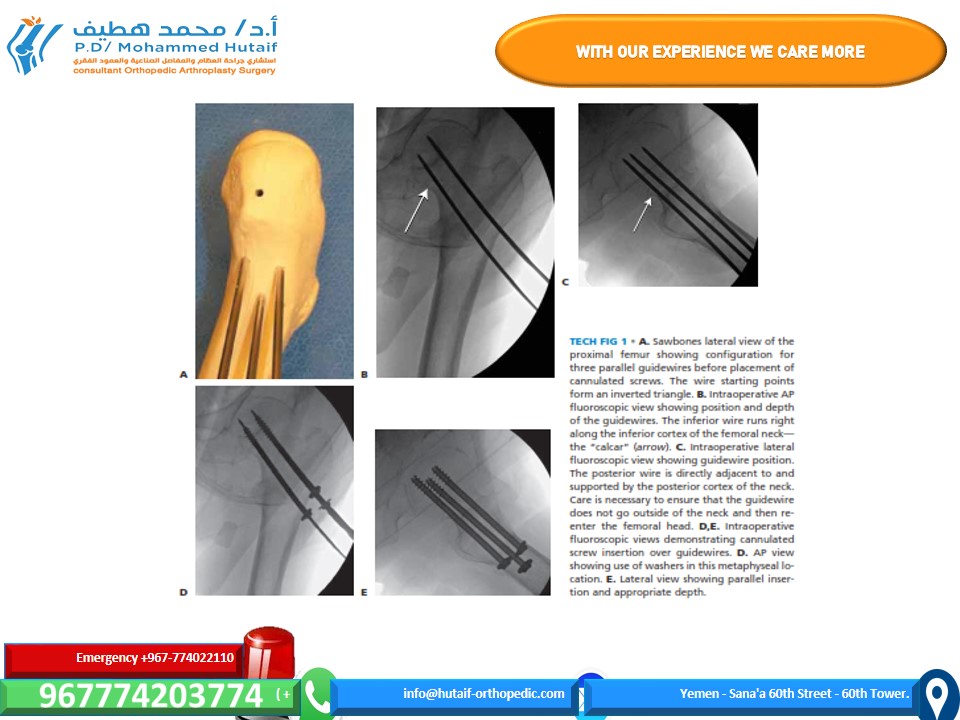
■ The standard screw arrangement is an inverted trian- gle of three screws.
■ They should be positioned peripherally in the femoral
neck with good cortical buttress, particularly against
the inferior and posterior neck. Starting points below the lesser trochanter should be avoided owing to risk of subtrochanteric fracture postoperatively (TECH FIG 1A–C).
■ Once the position of the wires is verified in two planes by
fluoroscopy, small (1-cm) full-depth incisions are made at each guide pin, and the soft tissues are spread to the bone.
■ The lateral cortex may be drilled in patients with dense
bone.
■ Self-drilling, self-tapping cannulated screws are placed by power over the guidewires.
■ Washers should be used in the more proximal, meta-
physeal locations (TECH FIG 1D,E).
■ Screws should be long enough so that all screw threads are on the proximal (head) side of the fracture.
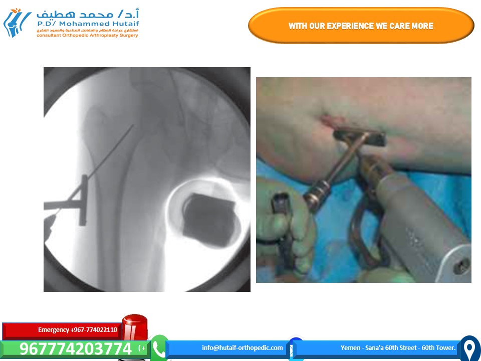
TECH FIG 1 • A. Sawbones lateral view of the proximal femur showing configuration for three parallel guidewires before placement cannulated screws. The wire starting points form an inverted triangle. B. Intraoperative AP fluoroscopic view showing position and depth of the guidewires. The inferior wire runs right along the inferior cortex of the femoral neck— the “calcar” (arrow). C. Intraoperative lateral fluoroscopic view showing guidewire position. The posterior wire is directly adjacent to and supported by the posterior cortex of the neck. Care is necessary to ensure that the guidewire does not go outside of the neck and then re- enter the femoral head. D,E. Intraoperative fluoroscopic views demonstrating cannulated screw insertion over guidewires. D. AP view showing use of washers in this metaphyseal lo- cation. E. Lateral view showing parallel inser- tion and appropriate depth.
Arthrotomy
■ Many surgeons believe that an arthrotomy should be performed to relieve pressure on the blood supply to the femoral head due to intracapsular bleeding. Some con- sider this to be mostly important in younger patients with minimally displaced fractures, because they reason that more widely displaced fractures have had decom- pression of the intracapsular hematoma by virtue of the injury. This is controversial.
■ A no.15 blade on a long handle is positioned at the
inferior margin of the base of the femoral neck on the AP fluoroscopic image.
■ A small skin incision is made at this level, and the soft tissues are spread down to the joint capsule.
■ With fluoroscopic verification of position, a small cap-
sulotomy is performed to allow drainage of the hematoma from the capsule.
■ A blunt sucker tip can be inserted through this small
incision to evacuate any remaining hematoma.
OPEN REDUCTION AND INTERNAL FIXATION THROUGH THE WATSON- JONES APPROACH
■ The patient is positioned on the fracture table as noted above, fluoroscopic visualization is confirmed, and the leg and hip is prepared and draped in a sterile fashion.
■ Circumferential proximal thigh preparation is
important.
■ Preoperative antibiotics are given.
Soft Tissue Dissection
■ The incision is located laterally over the anterior portion of the greater trochanter.
■ It curves slightly anteriorly as it extends proximal
from the trochanter toward the crest for about 8 to
10 cm.
■ It extends straight distally about 10 cm from the trochanter (TECH FIG 2A).
■ The fascia lata is identified and incised just posterior to
the tensor fascia lata muscle.
■ This incision through the fascia extends the length of the skin incision (TECH FIG 2B).
■ The anterior inferior edge of the gluteus minimus is
identified.
■ The interval between the minimus and the joint cap- sule is developed.
■ A portion of the minimus insertion on the trochanter
can be gently released to facilitate retraction with a curved blunt Hohmann retractor.
■ The reflected head of the rectus femoris is identified
(TECH FIG 2C) and divided (TECH FIG 2D), leaving a stump to repair.
■ A Cobb elevator can be used to clean muscle fibers off the anterior capsule.
■ The capsule is incised in line with the femoral neck axis
(TECH FIG 2E) and then released in a T shape along the acetabular edge (TECH FIG 2F).
■ Blunt Hohmann retractors can be moved inside the capsule. The surgeon must take care to be very gen- tle against the posterior femoral neck (TECH FIG
2G).
■ The fracture should be clearly exposed.
■ If necessary, the distal part of the capsule, where it inserts anteriorly at the base of the neck, can be released, converting the T arthrotomy to a lazy H (or an I).
■ This should be done gently and sparingly, and only if necessary for visualization, as it entails a risk of injury to the ring of vasculature at the base of the femoral neck.
Fracture Reduction
■ A 4.5-mm Schanz pin should be placed in the proximal femoral shaft at the subtrochanteric level to facilitate reduction. The use of a T-handle chuck will allow easier manipulation of this pin.
■ A 2.5-mm terminally threaded Kirschner wire is
placed in the femoral head at the articular margin to serve as a joystick in the proximal (head) fragment. Sometimes it is necessary to use two such joysticks to accurately position the head, which, because of its spherical nature, may be difficult to position along three axes simultaneously.
■ Reduction is performed under direct visualization using
the Kirschner wire and Schanz pin to manipulate the fragments.
■ Internal rotation of the shaft, along with external
rotation and adduction (valgusization) of the head fragment, is usually required.
■ Occasionally a bone hook under the medial inferior
portion of the neck will help.
■ The reduction is verified by keying the opposing cor- tical surfaces on the anterior, superior, and inferior neck together under direct visualization. A finger can be gently used to feel the surfaces and verify a smooth reduction without gaps or translation. Hard instruments should not be used for this to avoid dam- age to the delicate blood vessels on the neck.
■ The reduction is temporarily stabilized with at least two
terminally threaded 2.5-mm Kirschner wires placed from the lateral femoral cortex.
■ It is verified by fluoroscopy in two planes.
■ When the reduction is anatomic and temporarily stabi- lized, definitive fixation devices (cannulated screw guidewires, sliding hip screw, or cephalomedullary nail guide) are positioned.
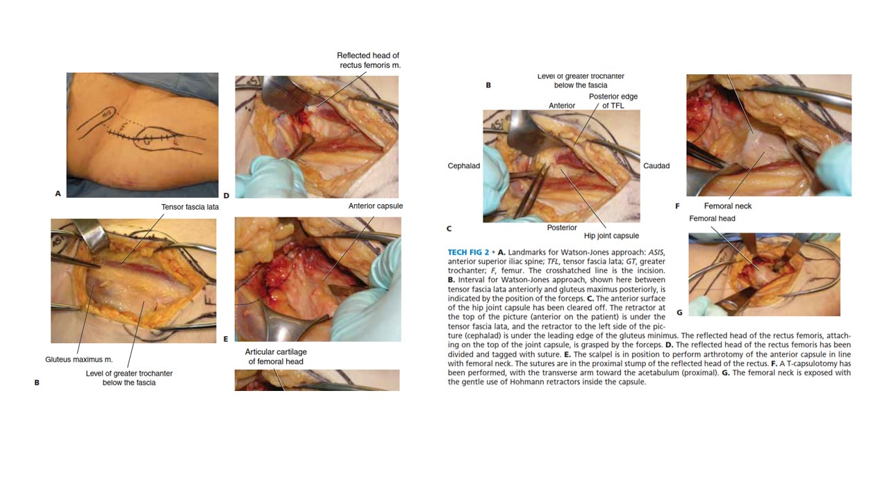
TECH FIG 2 • A. Landmarks for Watson-Jones approach: ASIS, anterior superior iliac spine; TFL, tensor fascia lata; GT, greater trochanter; F, femur. The crosshatched line is the incision. B. Interval for Watson-Jones approach, shown here between tensor fascia lata anteriorly and gluteus maximus posteriorly, is indicated by the position of the forceps. C. The anterior surface of the hip joint capsule has been cleared off. The retractor at the top of the picture (anterior on the patient) is under the G tensor fascia lata, and the retractor to the left side of the pic- ture (cephalad) is under the leading edge of the gluteus minimus. The reflected head of the rectus femoris, attach- ing on the top of the joint capsule, is grasped by the forceps. D. The reflected head of the rectus femoris has been divided and tagged with suture. E. The scalpel is in position to perform arthrotomy of the anterior capsule in line with femoral neck. The sutures are in the proximal stump of the reflected head of the rectus. F. A T-capsulotomy has been performed, with the transverse arm toward the acetabulum (proximal). G. The femoral neck is exposed with the gentle use of Hohmann retractors inside the capsule.
Screw Placement
■ Screw fixation is performed as described above for percutaneous stabilization.
■ For high-angle transcervical fractures (Pauwels 3), a lag screw should be positioned in a more horizontal orienta- tion, perpendicular to the fracture plane, to provide com- pression, which will resist the tendency for shear forces to displace the fracture.
■ Alternatively, a fixed-angle implant such as a sliding hip
screw or cephalomedullary nail could be used and may give better mechanical fixation in a comminuted fracture or Pauwels 3 fracture pattern.
■ Reduction and implant position should be verified with
the C-arm.
Wound Closure
■ Wound closure includes repair of the capsule, restoration of the reflected head of the rectus, and closure of the fascia lata.
■ Layered closure of the skin and sterile dressings com-
plete the job.
■ Portable radiographs in the operating room with the pa- tient still asleep, with the back table still sterile, are use- ful to avoid nasty surprises in the recovery room.
CEPHALOMEDULLARY NAIL FIXATION
■ The patient is positioned on the fracture table as noted above, fluoroscopic visualization is confirmed, and the leg and hip is prepared and draped in a sterile fashion.
■ Circumferential proximal thigh preparation is
important.
■ Preoperative antibiotics are given.
Incision and Dissection
■ A small incision, usually 3 to 4 cm long, is made several centimeters proximal to the tip of the greater trochanter to allow passage of the nail (TECH FIG 3).
■ A periosteal elevator can be used to spread the gluteus
medius fibers in line with the incision.
■ Blunt dissection with an elevator or a finger provides ac- cess to the starting point. The tip of the greater trochanter is palpated. The tendon of the gluteus medius attaching to the trochanter can be felt and is protected.
Starting Point and Reaming
■ Using fluoroscopy, a starting point is obtained for the nail at the medial edge of the greater trochanter for a trochanteric starting cephalomedullary nail.
■ The starting point should be just lateral to the piri-
formis fossa (TECH FIG 4A).
TECH FIG 3 • Landmarks for cephalomedullary nail place- ment. The iliac crest is marked and the trochanter is outlined. The incision is in line with the femoral shaft and several cen- timeters proximal to the tip of the trochanter.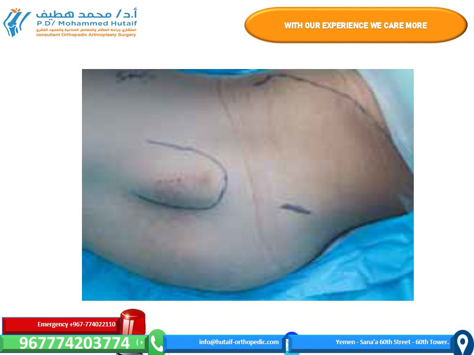
■ Alternatively, an awl can also be used to obtain the proper starting point; this can be especially useful in obese patients.
■ An anatomic reduction of the femoral neck must be
achieved before reaming.
■ If an anatomic reduction cannot be achieved by closed means, an open reduction must be performed.
■ This can be done by a Smith-Peterson or Watson-
Jones approach, as described above.
■ An antirotational pin may be used to maintain re- duction (TECH FIG 4B,C).
■ Once reduction has been obtained, the entry reamer is
introduced (TECH FIG 4D).
■ For a short cephalomedullary nail, the entry reamer is all that is needed before nail passage.
■ If a long cephalomedullary nail is being placed, serial
reaming can be performed to 1 to 1.5 cm over the de- sired nail diameter.
Proximal and Distal Interlocking
■ After the nail is positioned at the correct depth, the guidewire into the femoral head is placed.
■ Multiple fluoroscopic images are needed to make sure
the tip of the guidewire is placed within the center of the femoral head for nails with a single screw going into the head.
■ Newer nails with more than one screw going into
the head may necessitate adjustments to this tech- nique to allow passage of both screws (such as plac- ing the first lag screw slightly superior to center to allow passage of the second screw inferior to center).
■ A depth gauge is used to check the length of the
guidewire.
■ For rotationally unstable femoral neck fractures, an an- tirotational guidewire or screw can be placed to prevent rotation of the fracture with tapping (TECH FIG 5A).
■ Many nail systems allow a pin to be placed through a
sheath attached to the jig, or have an antirotational bar.
■ A reamer is then used to open the outer cortex of the
femur and is continued into the head under fluoroscopic guidance.
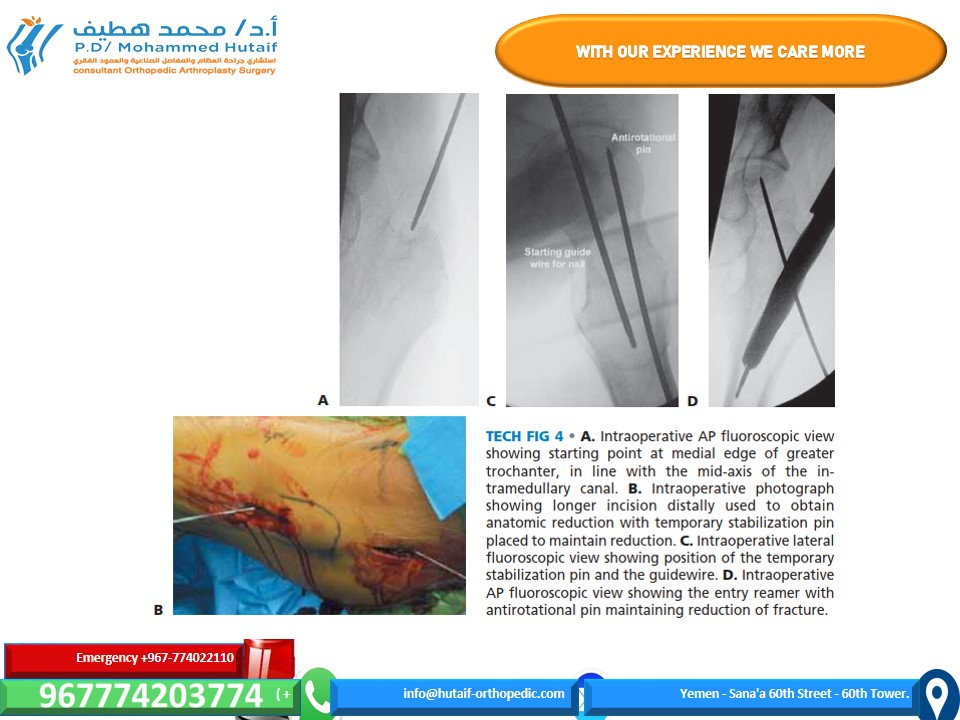
TECH FIG 4 • A. Intraoperative AP fluoroscopic view showing starting point at medial edge of greater trochanter, in line with the mid-axis of the in- tramedullary canal. B. Intraoperative photograph showing longer incision distally used to obtain anatomic reduction with temporary stabilization pin placed to maintain reduction. C. Intraoperative lateral fluoroscopic view showing position of the temporary stabilization pin and the guidewire. D. Intraoperative AP fluoroscopic view showing the entry reamer with B antirotational pin maintaining reduction of fracture.
■ The reamer should be checked during passage to en- sure the guidewire is not being driven into the pelvis and the reduction is not lost during reaming.
■ The lag screw is then tapped, and fluoroscopy is again
used to ensure the reduction is not lost.
■ The lag screw is placed and fluoroscopy undertaken in multiple views to rule out penetration of the subchon- dral surface.
■ If a distal interlock is desired, it is then placed.
■ Most nail systems have a set screw that needs to be ad- vanced to give rotational control to the lag screw.
■ If compression is desired, the set screw then needs to
be loosened, usually a quarter-turn of the screw- driver, according to the recommendations of the indi- vidual nail system being used.
■ As above, appropriate films should be taken with the pa-
tient asleep. This may include plain films if fluoroscopy is not adequate (TECH FIG 5B,C).
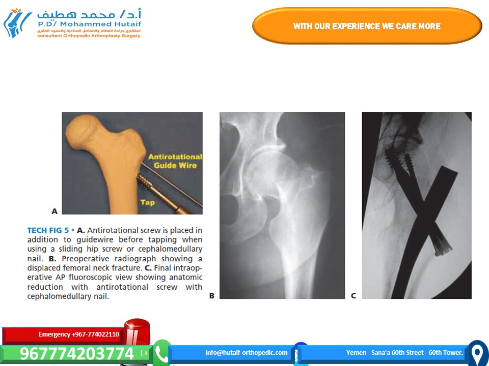
TECH FIG 5 • A. Antirotational screw is placed in addition to guidewire before tapping when using a sliding hip screw or cephalomedullary nail. B. Preoperative radiograph showing a displaced femoral neck fracture. C. Final intraop- erative AP fluoroscopic view showing anatomic reduction with antirotational screw with cephalomedullary nail.
MINIMALLY INVASIVE FIXATION WITH A SLIDING HIP SCREW
Positioning, Reduction, and
Guidewire Placement
■ The patient is positioned on the fracture table as noted above and in Chapter TR-8, except that we do not use a well leg holder because of risk of compartment syndrome. Occasionally, in patients with adduction contracture, the well leg cannot be abducted enough with the hip extended to allow access of the C-arm. In these cases, the well leg holder is used as described in Chapter TR-15. Fluoroscopic visualization is performed, and reduction is confirmed to be acceptable in all planes.
■ In femoral neck fractures, as opposed to in-
tertrochanteric or pertrochanteric fractures, the reduc- tion must be verified as anatomic if one is to expect sta- bility and healing.
■ In this approach, as opposed to the technique described
in Chapter TR-15, the guidewire is inserted percuta- neously by poking through the skin under the guidance of fluoroscopy and with use of an appropriate angle guide (TECH FIG 6A).
■ The guidewire is positioned in the center of the femoral
neck and head as described in Chapter TR-15 (TECH FIG 6B).
■ If the fracture is rotationally unstable (transcervical, com- minuted, widely displaced before reduction), an antiro- tational wire or screw should be placed up the neck across the fracture to prevent loss of reduction (see Tech Fig 5A).
Incision and Preparation of Bone
■ An incision is made beginning at the guidewire and ex- tending distally for 4 to 5 cm (TECH FIG 7A).
■ A full-thickness skin-to-bone incision is made.
■ Soft tissues are gently spread with a clamp, and an el- evator is used to clear tissue from the lateral cortex distal to the pin entry site for the length of a two- hole plate.
■ The guidewire is measured.
■ The reamer is then set to this depth (TECH FIG 7B).
■ Fluoroscopy should be checked intermittently during reaming because the guidewire can migrate into the pelvis if bound by the reamer.
Implant Placement
■ The lag screw is then placed over the guidewire in stan- dard fashion (TECH FIG 8).
■ The femoral neck–shaft angle has been set by placement
of the guide pin, but it can be measured intraoperatively with a guide to select the appropriate implant.
■ This is usually a 135-degree side plate if placed
correctly.
■ The side plate is then placed over the lag screw and gen- tly worked through the soft tissues until it is placed into
contact with the lateral cortex. The skin is quite mobile and elastic, and with a little stretching the plate can be positioned easily.
■ Final seating can be done with light blows of a mallet
with the aid of a “candlestick” impaction device.
■ A two-hole plate is sufficient.
■ If lag screw was not placed with the key parallel to the femoral shaft, most systems allow this to be corrected by
simply reapplying the T-handle screwdriver to the lag screw and turning the plate and screw as one unit until the plate fits appropriately.
■ Usually only two bicortical screws are needed through
the side plate into the shaft.
■ As above, appropriate films should be taken with the pa- tient asleep. This may include plain films if fluoroscopy is not adequate.
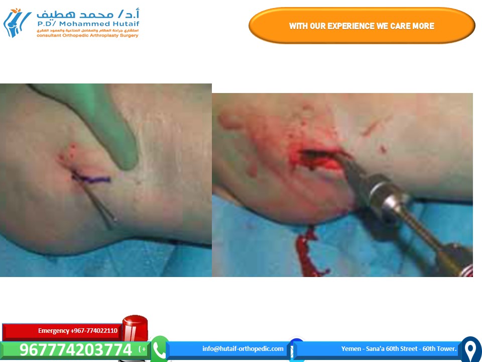
TECH FIG 6 • A. Percutaneous insertion of a guidewire with angle guide. The guide is held alongside the leg and fluoro- scopic views are obtained to verify parallel alignment. B. Fluoroscopic AP image showing insertion of guidewire, which has been stabbed through the skin.
TECH FIG 7 • A. After satisfactory position of the guidewire is verified on AP and lateral fluoroscopy, the incision is marked on the skin 4 to 5 cm inferior to the guidewire. B. The cannulated reamer is used to prepare the bone for the lag screw.
PEARLS AND PITFALLS
Imaging ■ The pattern of injury must be recognized preoperatively. A traction film with internal rotation can help with this, as initial plain films are usually externally rotated and may be difficult to interpret.
■ If the clinical examination is suspicious despite negative plain films, a screening MRI is indicated to rule out an occult femoral neck fracture.
■ Although controversial, a CT scan of the femoral neck should be considered in all trauma patients with femur fractures.
Positioning ■ Pelvic rotation: Either scissor legs with the fracture table, or the torso is leaned away from the affected side to pre- vent pelvic tilt.
■ The patients should be draped wide, from the lower ribs to below the knee, to allow complete access to the femur if problems arise.
Reduction ■ Internal rotation of the fractured-side leg holder will reduce anterior neck diastasis.
■ Guidewire joysticks using 2.5-mm terminally threaded Kirschner wires and Schanz pins can be used to help obtain reduction (usually used when an open reduction is necessary).
■ Reduction is facilitated by complete muscle relaxation.
■ An anatomic reduction is necessary. An open approach should be used if there is any question that the reduction is not perfect.
Fixation ■ The surgeon should avoid starting screws inferior to the lesser trochanter to minimize the risk of subtrochanteric femur fracture.
■ Screws are positioned against the femoral neck cortex, especially inferiorly and posteriorly.
■ For high-angle fractures (Pauwels type 3), the surgeon should consider using an additional horizontal screw, sliding hip screw, or cephalomedullary nail.
■ If the fracture is comminuted or rotationally unstable, the surgeon should consider placing a sliding hip screw or cephalomedullary nail.
■ If using a sliding hip screw or cephalomedullary nail, the tip–apex distance should be 25 mm or less, calculated by adding the distance from the center of the femoral head at the level of the subchondral bone to the tip of the screw on both the AP and lateral radiographs.
POSTOPERATIVE CARE
■ In the elderly, mentally competent patient with stable fixa- tion, weight bearing is allowed as tolerated.
■ For deep vein thrombosis prophylaxis, the length and type of treatment are controversial, but some form of prophylaxis should be given at least during the patient’s hospital stay.
■ A first-generation cephalosporin is given for 24 hours post- operatively.
OUTCOMES
■ The 1-year mortality rate is about 20% in the elderly.4
■ About 50% of patients return to their previous level of function.3
COMPLICATIONS
■ There is a 16% rate of avascular necrosis with displaced femoral neck fractures.2
532 Part 2 PELVIS AND LOWER EXTREMITY TRAUMA • Section I PELVIS AND HIP
■ There is a 33% rate of nonunion with displaced femoral neck fractures.2
REFERENCES
1. Cummings SR, Rubin SM, Black D. The future of hip fractures in the United States: numbers, costs, and potential effects of postmenopausal estrogen. Clin Orthop Relat Res 1990;252:163–166.
2. Lu-Yao GL, Keller RB, et al. Outcomes after displaced fractures of the femoral neck: a meta-analysis of 106 published reports. J Bone Joint Surg Am 1994;76A:15–25.
3. Pajarinen J, Lindahl J, et al. Pertrochanteric femoral fractures treated with a dynamic hip screw or a proximal femoral nail. J Bone Joint Surg Br 2005;87B:76–81.
4. Rogmark C, Johnell O. Primary arthroplasty is better than internal fixation of displaced femoral neck fractures. Acta Orthop 2006;77:
359–367.
5. Verheyen CC, Smulders TC, van Walsum AD. High secondary dis- placement rate in the conservative treatment of impacted femoral neck fractures in 105 patients. Arch Orthop Trauma Surg 2005;125:
166–168.